
Automatic alert device for suction cup

a technology of automatic alert device and suction cup, which is applied in the direction of machine supports, manufacturing tools, instruments, etc., can solve the problems of inability to monitor the red line, accidents due to insufficient suction force, and troublesome jobs, etc., to achieve convenient operation, practical and safe

Inactive Publication Date: 2010-03-09
LIH YANN INDAL
View PDF4 Cites 17 Cited by
  • Summary
  • Abstract
  • Description
  • Claims
  • Application Information

AI Technical Summary

Benefits of technology

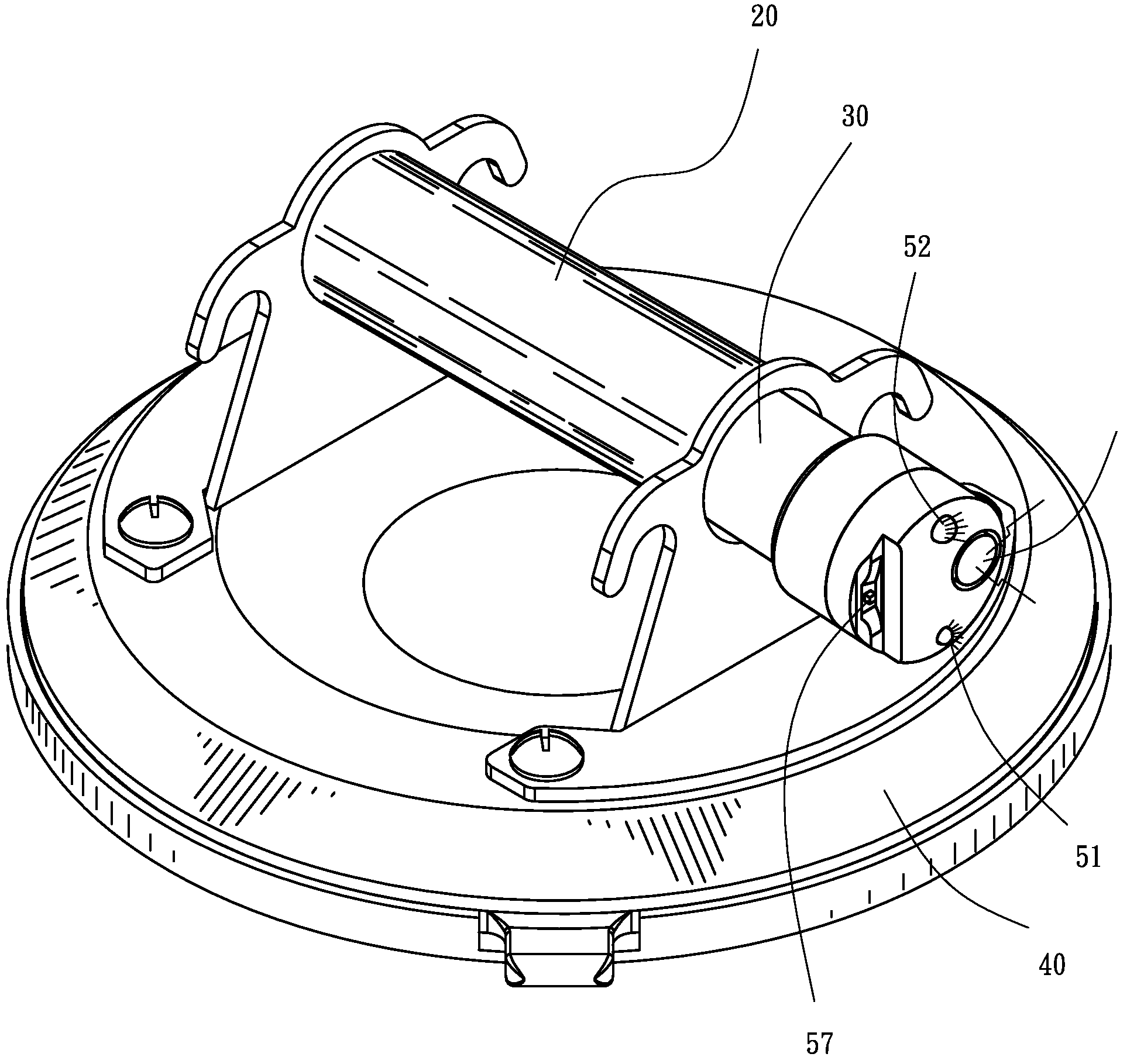
"The present invention provides an automatic alert device for a suction device. The device includes a suction cup and a pump integrated with the suction cup. The device is designed to induce suction force on an object by moving a plunger inside the pump. When the suction force is gradually reduced, the plunger moves out of the pump and exposes a red line, indicating that the plunger needs to be re-operated to increase the suction force. The invention provides an easy-to-operate and practical solution to the problem of insufficient suction force, which can occur unexpectedly and lead to safety issues. The actuation bar is operatively coupled to the plunger, so that when the plunger moves out of the pump, the actuation bar also moves to trigger the sensor and activate the alert device, providing warnings of light and sound to notify the operator of the situation of insufficiency of suction force, which can then get timely attention to avoid potential safety problems."

Problems solved by technology

This is a troublesome job.
Further, in case that the suction device is set a location far away from the operator, such as located at a raised position, or the operator has to leave for a long while, the red line can no longer be watched and accidents due to insufficiency of suction force may happen unexpectedly.
The prior art requires constant observation of the plunger to check if the red line gets exposed in order to re-operate the suction device to maintain the desired level of suction force, and this indicates that once the plunger is not or cannot be constantly monitored and is set at a location far away from an operator, safety problem may unexpectedly occur due to the unattended exposure of the red line of the plunger.

Method used


Image

  • Automatic alert device for suction cup
  • Automatic alert device for suction cup
  • Automatic alert device for suction cup

Examples


Embodiment Construction

[0020]With reference to the drawings and in particular to FIGS. 7 and 8, a suction cup, generally designated with reference numeral 40, in which an automatic alert device constructed in accordance with the present invention is embodied is. The suction cup 40 comprises a pumping device (or simply “pump”) integrated therewith and the pump comprises a cylinder 20 in which a plunger 30 is movably received. The automatic alert device constructed in accordance with the present invention, generally designated with reference numeral 50, is formed on an outer end of the plunger 30 and is generally exposed outside the cylinder 20.

[0021]Also referring to FIG. 3, which shows a cross-sectional view of the plunger 30, the plunger 30 to which the alert device 50 is mounted comprises a barrel 33 having an axially inner end opposite to the outer end that carries the alert device 50. Axially arranged in barrel 33 are a central rod 31 and a resilient element 32 having opposite ends engaging the inner ...


PUM


Abstract

An automatic alert device is provided for a suction cup, including a pump and a suction cup positionable on an object to be handled. The pump is operable to drive air out of the suction cup thereby inducing suction force on the object to be handled. When the suction cup gradually loses the suction force, a plunger of the pump gets moved out of the pump. When the outward movement of the plunger reaches a preset extent, the alert device that includes a warning light and an audio alert is activated to cause the warning light and the audio alert to give off warnings of light and sound respectively. Thus, an operator can be immediately notified of the situation of losing suction force for taking remedial operation to get the suction force back to the desired level.

Description

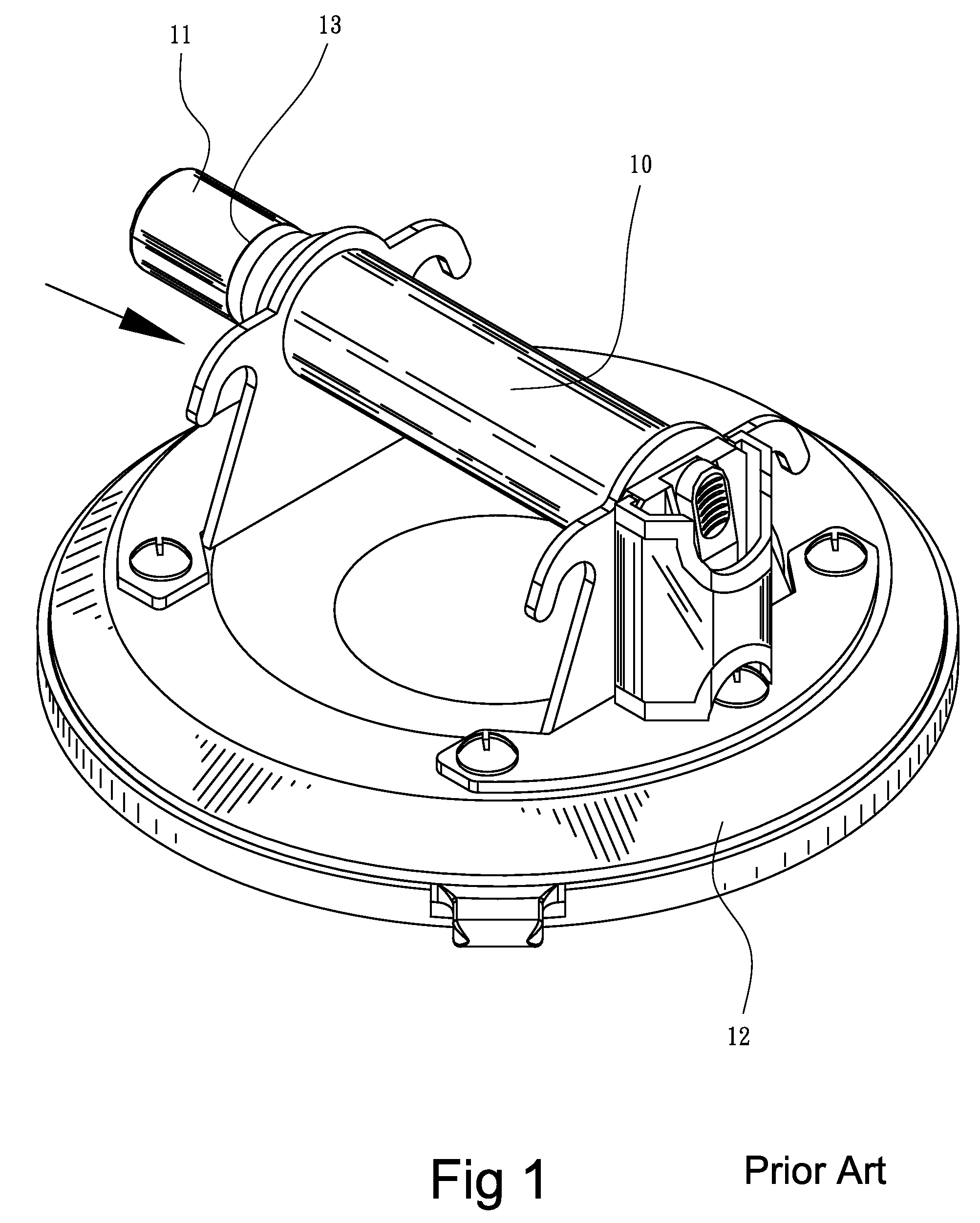
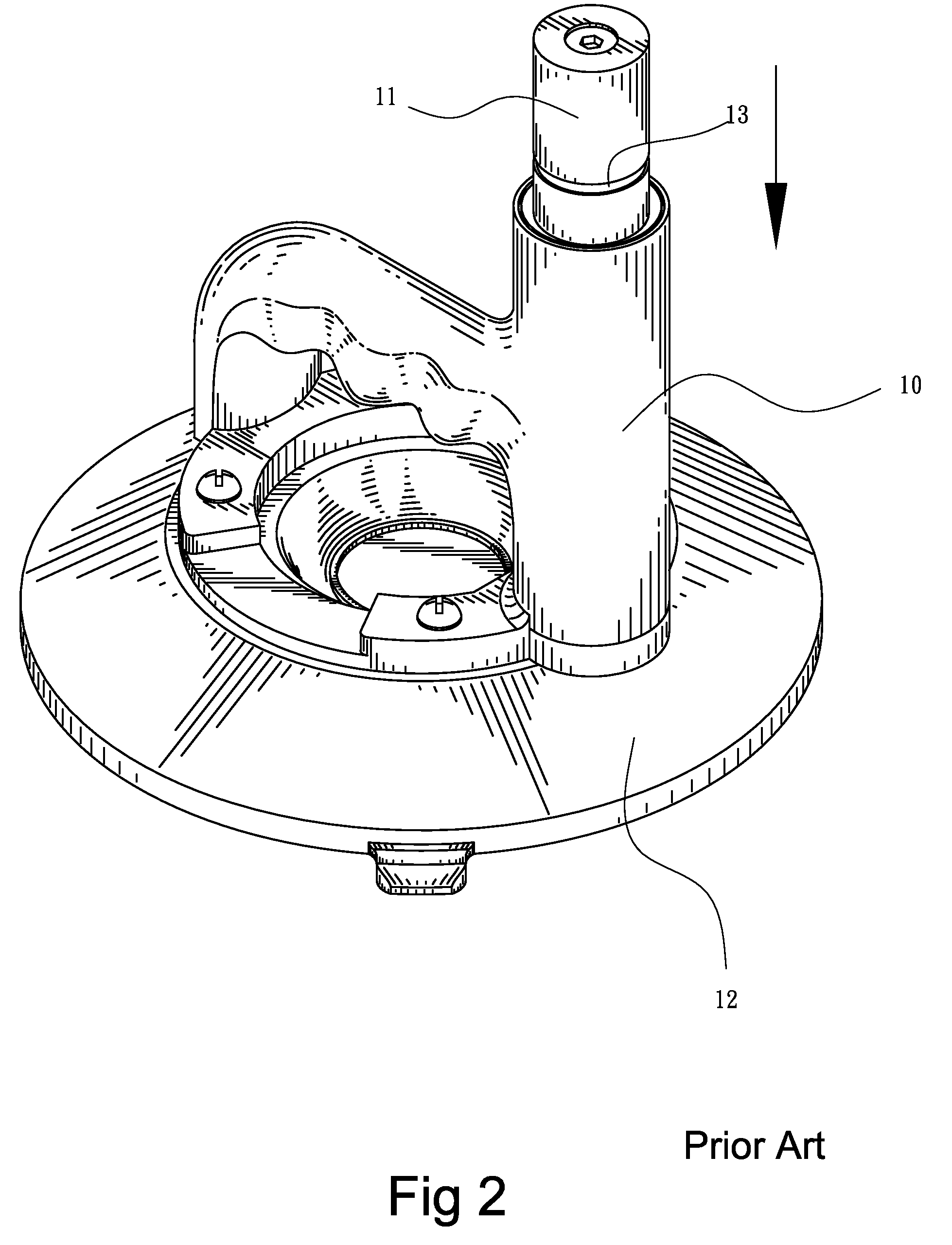
BACKGROUND OF THE INVENTION[0001]1. Field of the Invention[0002]The present invention relates to an alert device for a suction device, and in particular to an automatic alert device that generates warnings of light and sound to indicate an excessive reduction of suction force of the suction device.[0003]2. The Related Arts[0004]Suction devices are commonly known and widely used to handle objects having a flat and smooth surface. FIGS. 1 and 2 illustrate a conventional pump-contained suction device, wherein a pump for expelling air out of the suction device is integrated to the suction device. The pump can be horizontally arranged (FIG. 1), where the pump has an axis substantially parallel to the surface of the object to be handled; or alternatively, the pump can be vertically arranged (FIG. 2), where the axis of the pump is arranged perpendicular to the surface to be handled. Both types of pump comprise a plunger 11 reciprocally movable within the pump 10. The plunger 12 is forcibly...

Claims


Application Information

Patent Timeline
Patent Type & Authority Patents(United States)
IPC IPC(8): B25J15/06
CPCF16B47/00Y10S294/907
Inventor LIAO, PO LIN
Owner LIH YANN INDAL
Learn More