LED lighting device capable of uniformly dissipating heat

a technology of led lighting and heat dissipation device, which is applied in the direction of lighting and heating apparatus, semiconductor devices for light sources, and light support devices. it can solve the problems of fan consuming extra electricity when operated, disadvantageous influence on service life, and limited service life, and achieves simple structure, high thermal conductivity, and light weight

Active Publication Date: 2010-03-09
KITAGAWA HLDG
View PDF8 Cites 61 Cited by
  • Summary
  • Abstract
  • Description
  • Claims
  • Application Information

AI Technical Summary

Benefits of technology

[0007]It is a primary object of the invention to provide an LED lighting device, which conducts the heat generated from the LED lighting modules to both heat dissipating fins and a top cover uniformly and rapidly.
[0009]In comparison with the conventional LED lighting device, the present invention is provided with two heat dissipating modules, in which one heat dissipating module transfers the heat to the dissipaters by a heat-conducting plate and heat pipes, and the other heat dissipating module concurrently transfers the heat to the top cover. The two heat dissipating modules are lined on the LED lighting modules for transferring the heat uniformly and rapidly. Because the heat pipe has advantages of high thermal conductivity, light weight, simple structure and long service time, it has an excellent heat conducting efficiency without consuming extra electricity, which make economical and practical utility be improved.

Problems solved by technology

For a conventional mercury-vapor streetlamp, the high heat resulting from overnight use always makes its service life limited.
However, the heat generated from the LED will have disadvantageous influence on its service life.
But the fan requires consuming extra electricity when operated, which contradicts the conception of power saving and environment protecting.
In addition, the fan installed outdoors may be damaged easily.

Method used


Image

  • LED lighting device capable of uniformly dissipating heat
  • LED lighting device capable of uniformly dissipating heat
  • LED lighting device capable of uniformly dissipating heat

Examples


Embodiment Construction

[0019]The technical characteristics, features and advantages of the present invention will become apparent in the following detailed description of preferred embodiments with reference to the accompanied drawings, and the preferred embodiments are used for illustrating the present invention only, but not intended to limit the scope of the present invention.

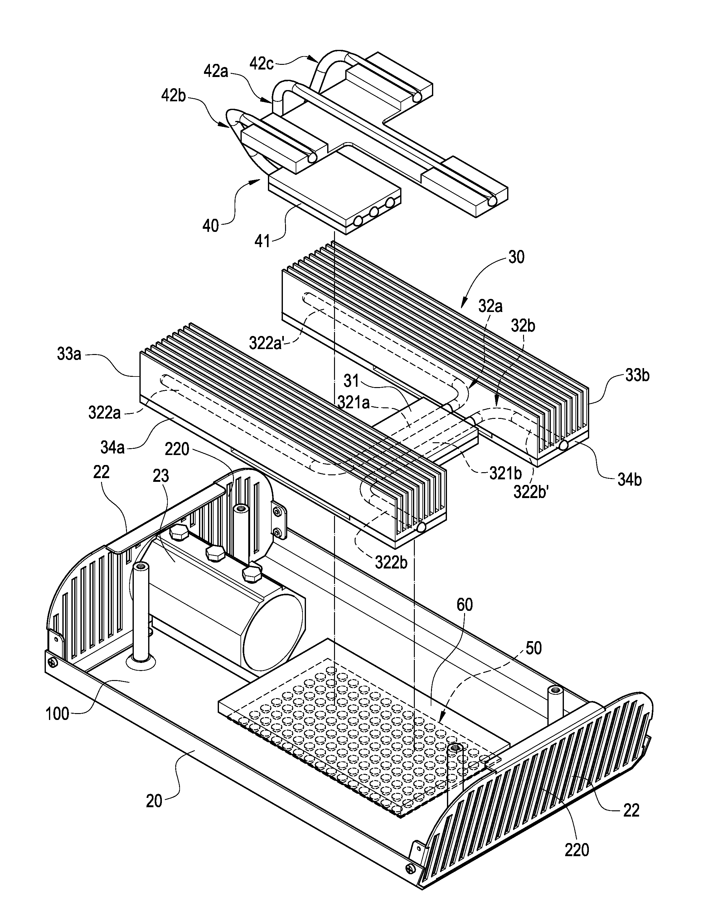
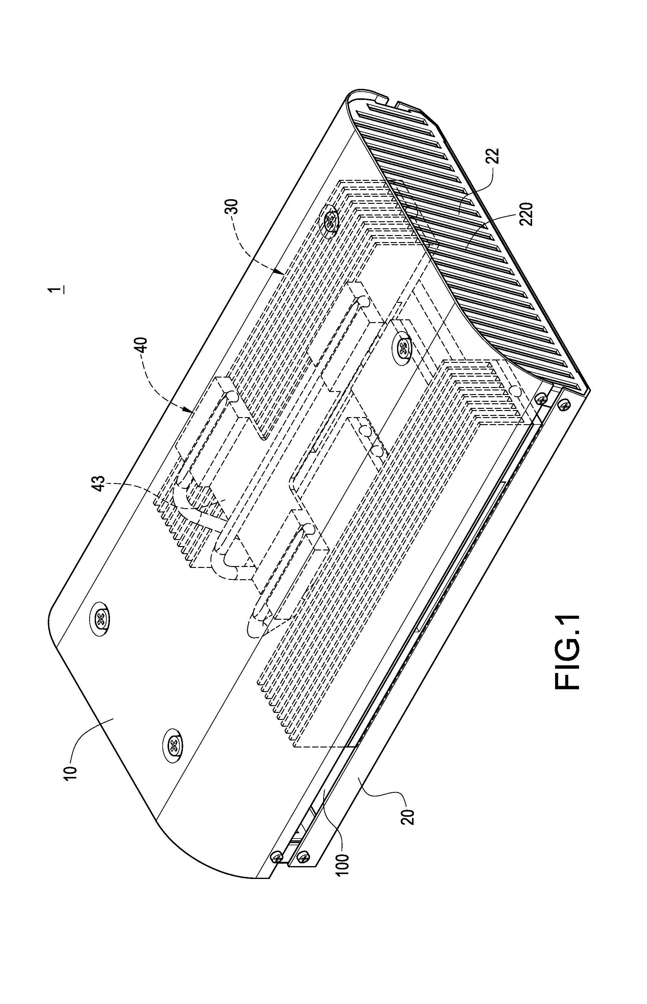
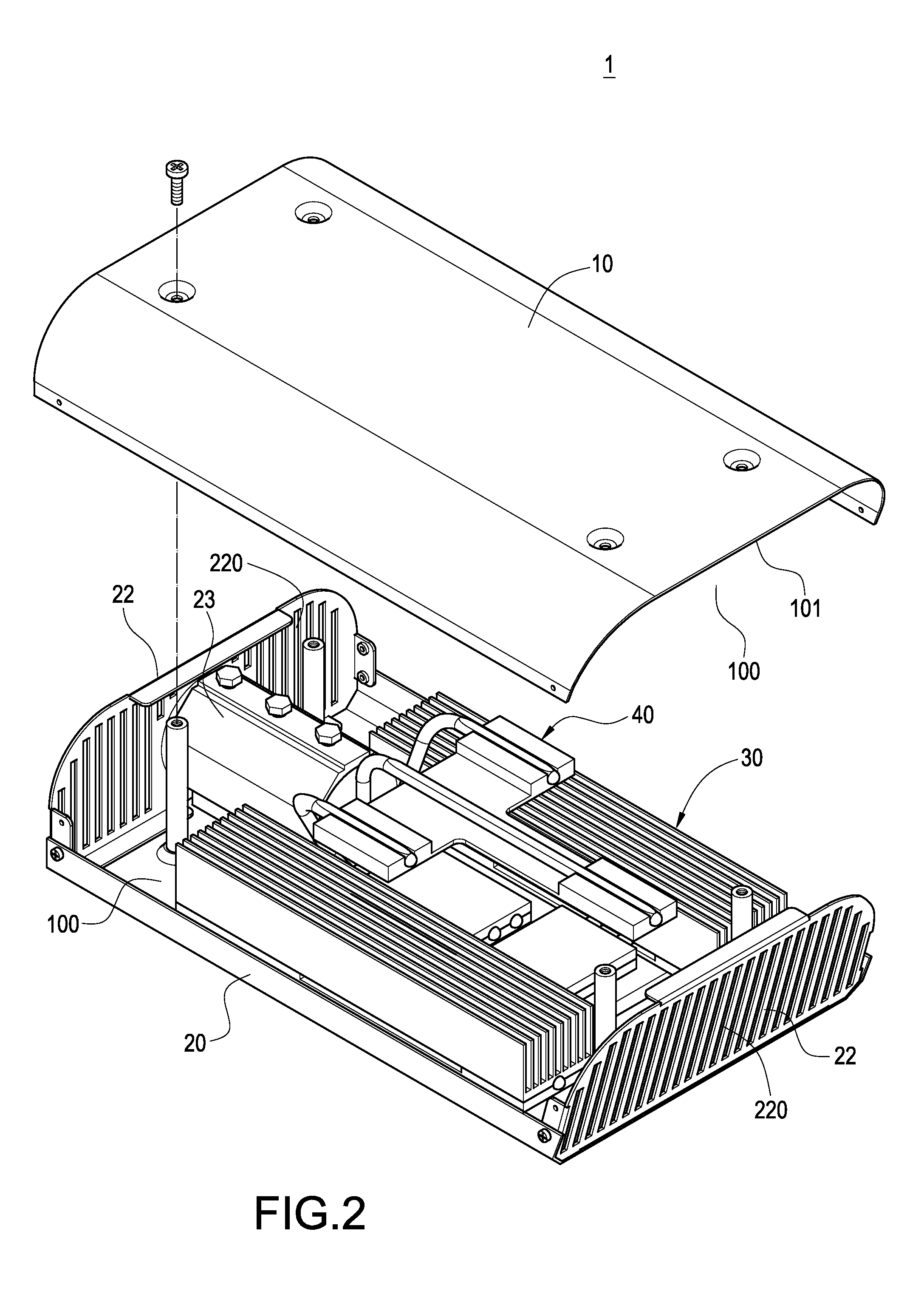
[0020]With reference to FIG. 1, the present invention is a light-emitting diode (LED) lighting device 1. The lighting device 1 includes a top cover 10 and a lamp base 20. The lamp base 20 is coupled with the top cover 10 to form an accommodating space 100 for accommodating a first heat dissipating module 30 and a second heat dissipating module 40. The first heat dissipating module 30 and the second heat dissipating module 40 are arranged inside the lamp base 20.

[0021]With further reference to FIG. 2, two corresponding ends of the lamp base 20 are provided with side plates 22 separately. There are a plurality of heat dissipating ho...


PUM


Abstract

An LED lighting device with a heat dissipating structure is disclosed. The lighting device includes a lamp base coupled with a top cover to form an accommodating space for accommodating a first heat dissipating module and a second heat dissipating module. The first heat dissipating module includes a first heat-conducting plate, a first heat pipe and a first heat dissipater. An LED lighting module is connected with the first heat-conducting plate, in which an evaporator section of the first heat pipe is disposed thereon. The first heat dissipater is arranged on a condenser section of the first heat pipe, and the second heat dissipating module includes a second heat-conducting plate and a second heat pipe. The second heat-conducting plate paralleling to the first heat-conducting plate is connected with the LED lighting module. An evaporator section of the second heat pipe is disposed on the second heat-conducting plate, and whose condenser section is connected with an inner surface of the top cover. Whereby, the heat generated from the LED lighting module can be dissipated uniformly and rapidly.

Description

BACKGROUND OF THE INVENTION[0001]1. Field of the Invention[0002]The present invention generally relates to an LED lighting device, and more particularly to an LED streetlamp having a heat dissipating structure.[0003]2. Description of Prior Art[0004]For a conventional mercury-vapor streetlamp, the high heat resulting from overnight use always makes its service life limited. Because of its high power consuming and environmental pollution, it trends toward being replaced by a light emitting diode (LED) lighting device having advantages of high intensity, power saving and long service life, etc. However, the heat generated from the LED will have disadvantageous influence on its service life. Therefore, the LED streetlamps usually employ heat dissipating devices.[0005]A conventional LED streetlamp is provided with a lamp base and a transparent cover, in which a plurality of LEDs are accommodated therebetween. A heat dissipating device comprising a heat-conducting plate and plural heat di...

Claims


Application Information

Patent Timeline
Patent Type & Authority Patents(United States)
IPC IPC(8): F21V29/00
CPCF21V29/004F21V29/006F21V29/83F21V29/717F21V29/763F21Y2101/02Y10S362/80F21Y2115/10F21V29/51
Inventor LIN, KUO-LENLIN, CHEN-HSIANGHUNG, MONG-HUAHUANG, CHIAO-LIHSU, KENCHENG, CHIH-HUNG
Owner KITAGAWA HLDG
Why Eureka
Try Eureka