Shadow mask tensioning method

a mask and tensioning technology, applied in the field of patterned physical vapor deposition, can solve the problems of difficult control of the method of tensioning, deformation of the mask, and non-uniform tension of the mask, and achieve the effect of producing extremely uniform tension throughout the mask, low cost of production, and reliable operation

Active Publication Date: 2010-03-09
GLOBAL OLED TECH
View PDF5 Cites 7 Cited by
  • Summary
  • Abstract
  • Description
  • Claims
  • Application Information

AI Technical Summary

Benefits of technology

[0015]The shadow mask tensioning method of this invention has the advantage that it produces extremely uniform tension throughout the entire mask. It has the further advantage that the equipment required to by the invention is mechanically quite simple and is therefore low cost to make, requires virtually no maintenance or calibration, and is extremely reliable in operation.

Problems solved by technology

These existing methods for tensioning are difficult to control in a manner that results in uniform tension within the tensioned shadow mask.
The portion of the mask which is in direct contact with the clamp bars cannot stretch, and therefore introduce non-uniformities in the mask tension.
Non-uniform tension leads to deformations within the mask, which contains a larger number of openings, often with very tight tolerances.
The existing methods rely on mechanisms with moving parts, sometimes with complex controls, and are subject to a wide variety of failure mechanisms.

Method used


Image

  • Shadow mask tensioning method
  • Shadow mask tensioning method
  • Shadow mask tensioning method

Examples


Embodiment Construction

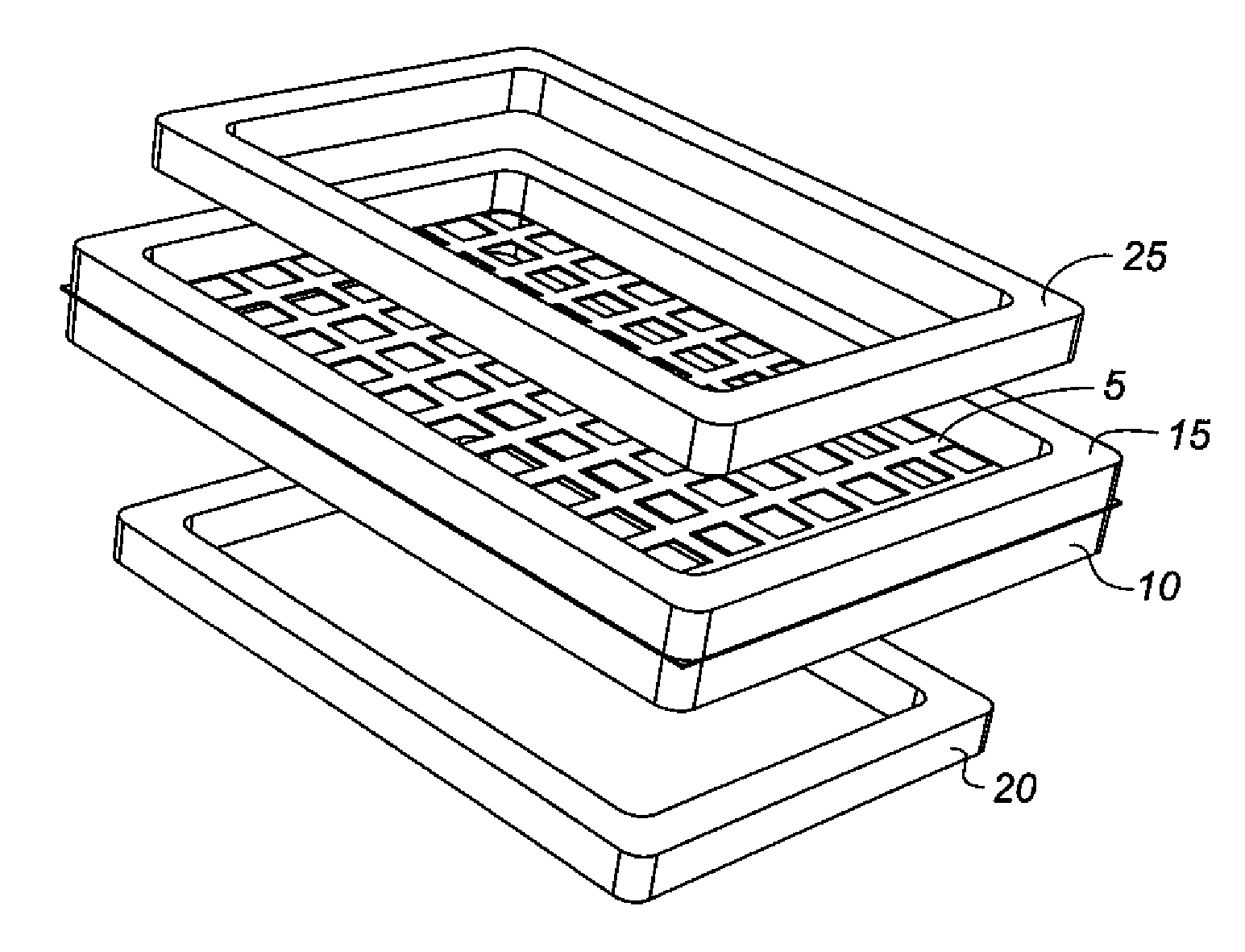
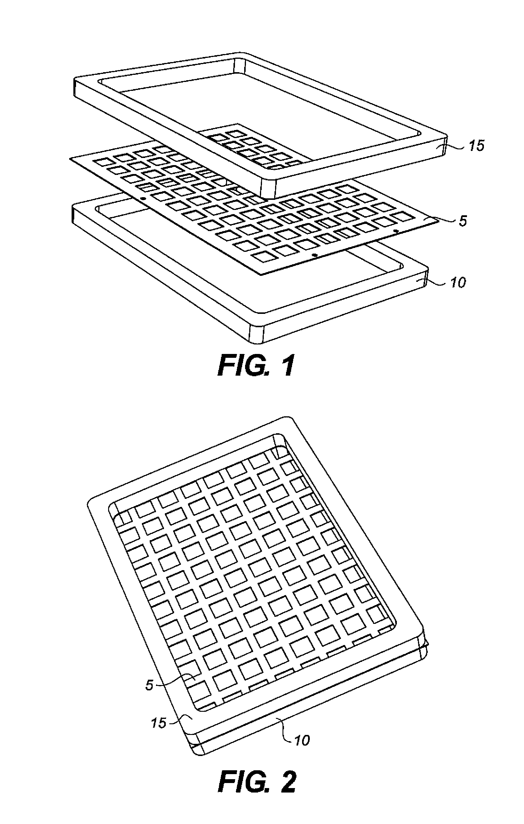
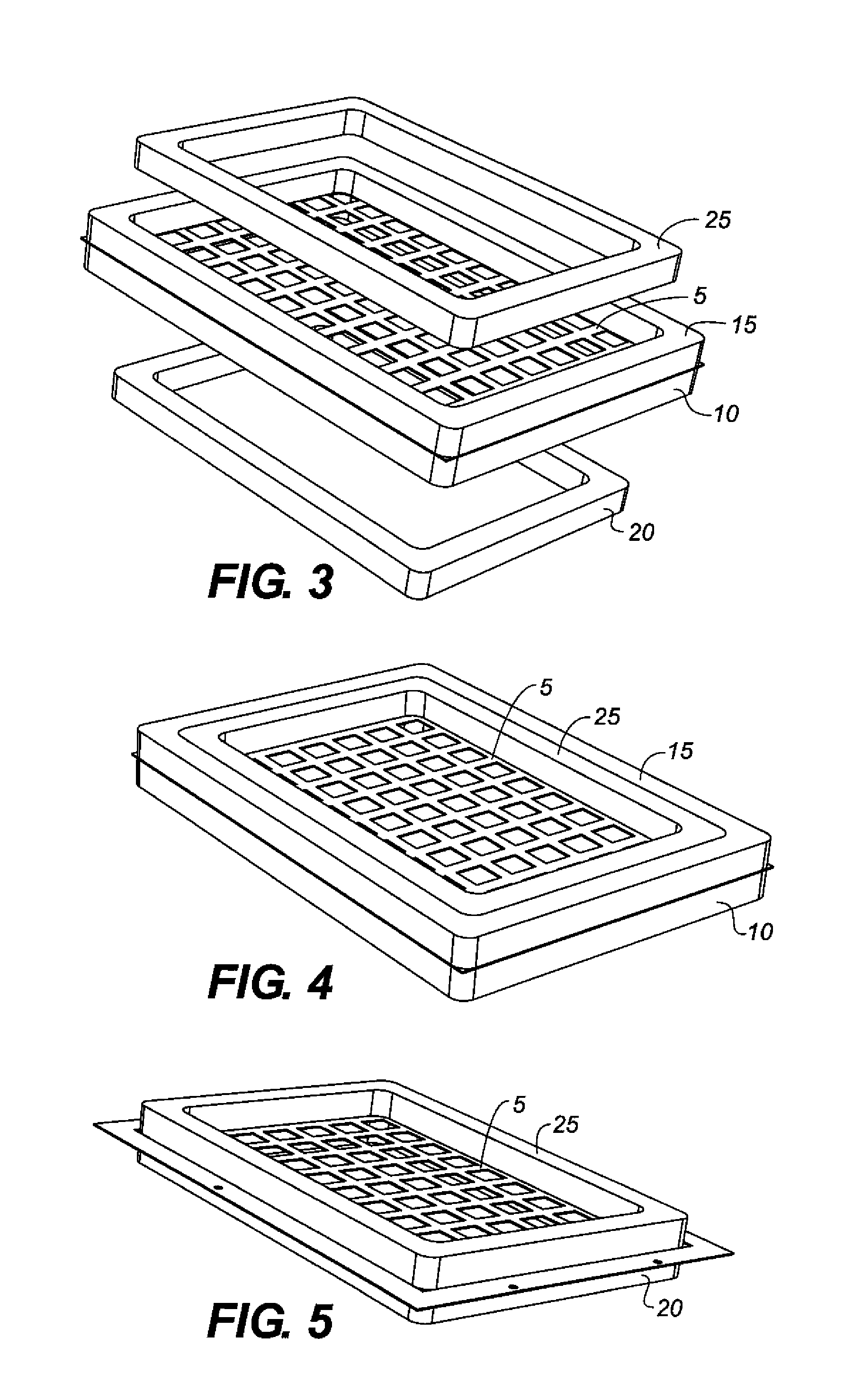
[0021]Referring to FIG. 1, one side of a shadow mask 5 is brought into contact with the tension frame lower half 10. The tension frame upper half 15 is then brought into contact with the second side of the shadow mask 5. FIG. 2 shows the assembled shadow mask and upper and lower tension frame halves. The two tension frame halves are then rigidly clamped together. There are any number of ways available to achieve this clamping that are well known to those of ordinary skill in the art and include bolts, external clamps, magnets / electromagnets, and lever action mechanisms.

[0022]Once the two tension frame halves are clamped together, they are heated to an elevated temperature, causing them to expand and tension the shadow mask 5. The heat for this process can be from external heat sources such as induction coils, infrared radiant heaters or contact electrical heaters, or it can be from an internal heat source embedded within the frame, such as an embedded or internal electric cartridge ...


PUM

PropertyMeasurementUnit
temperatureaaaaaaaaaa
tensionaaaaaaaaaa
forcesaaaaaaaaaa

Abstract

A method for tensioning a shadow mask includes positioning a first side of a shadow mask into contact with the lower half of a tensioning frame, positioning an upper half of the tensioning frame into contact with a second side of the shadow mask, and clamping the upper half of the tensioning frame to the lower half of the tensioning frame to form a tensioning frame, and rigidly clamping the shadow mask between the two tensioning frame halves. The method also includes elevating the temperature of the tensioning frame to tension the shadow mask.

Description

FIELD OF INVENTION[0001]This invention relates to patterned physical vapor deposition. More specifically, this invention relates to providing uniform tension in a shadow mask.BACKGROUND OF THE INVENTION[0002]Physical vapor deposition (PVD) is a useful technique for producing thin films, enabling the fabrication of devices such as organic light emitting diodes (OLEDs) and photovoltaic devices (“solar cells”). Shadow masks are used to pattern the thin films during the deposition process. In general, there is a need for precision alignment between the various layers deposited in the fabrication of complex, layered structures such as OLEDs. Providing uniform tension in the shadow mask is an essential contributor to enabling precision alignment, especially in designs that use multiple shadow masks.[0003]Existing methods for tensioning a shadow mask rely primarily on mechanisms in which clamp bars are affixed to the edges of the shadow mask and forces are applied to these clamp bars via p...

Claims


Application Information

Patent Timeline
Patent Type & Authority Patents(United States)
IPC IPC(8): H01J9/236
CPCC23C14/042H01L51/0011H01L51/42H01L51/56H10K71/166H10K30/00H10K71/00
Inventor GRIFFIN, TODD R.PALONE, THOMAS W.
Owner GLOBAL OLED TECH
Why Eureka
Try Eureka