
Method and apparatus for compensating for motion prediction

Inactive Publication Date: 2010-03-09
SONY CORP
View PDF14 Cites 29 Cited by
  • Summary
  • Abstract
  • Description
  • Claims
  • Application Information

AI Technical Summary

Benefits of technology

[0013]It is an object of the present invention to provide a method and apparatus for compensating for motion prediction which can reduce the process burden due to code processing while possibly avoiding the lowering image quality.

Problems solved by technology

Thus, the present inventors have recognized that there is a drawback that process burden is increased due to code processing.

Method used


Image

  • Method and apparatus for compensating for motion prediction
  • Method and apparatus for compensating for motion prediction
  • Method and apparatus for compensating for motion prediction

Examples


Embodiment Construction

JVT Coding Scheme Overview

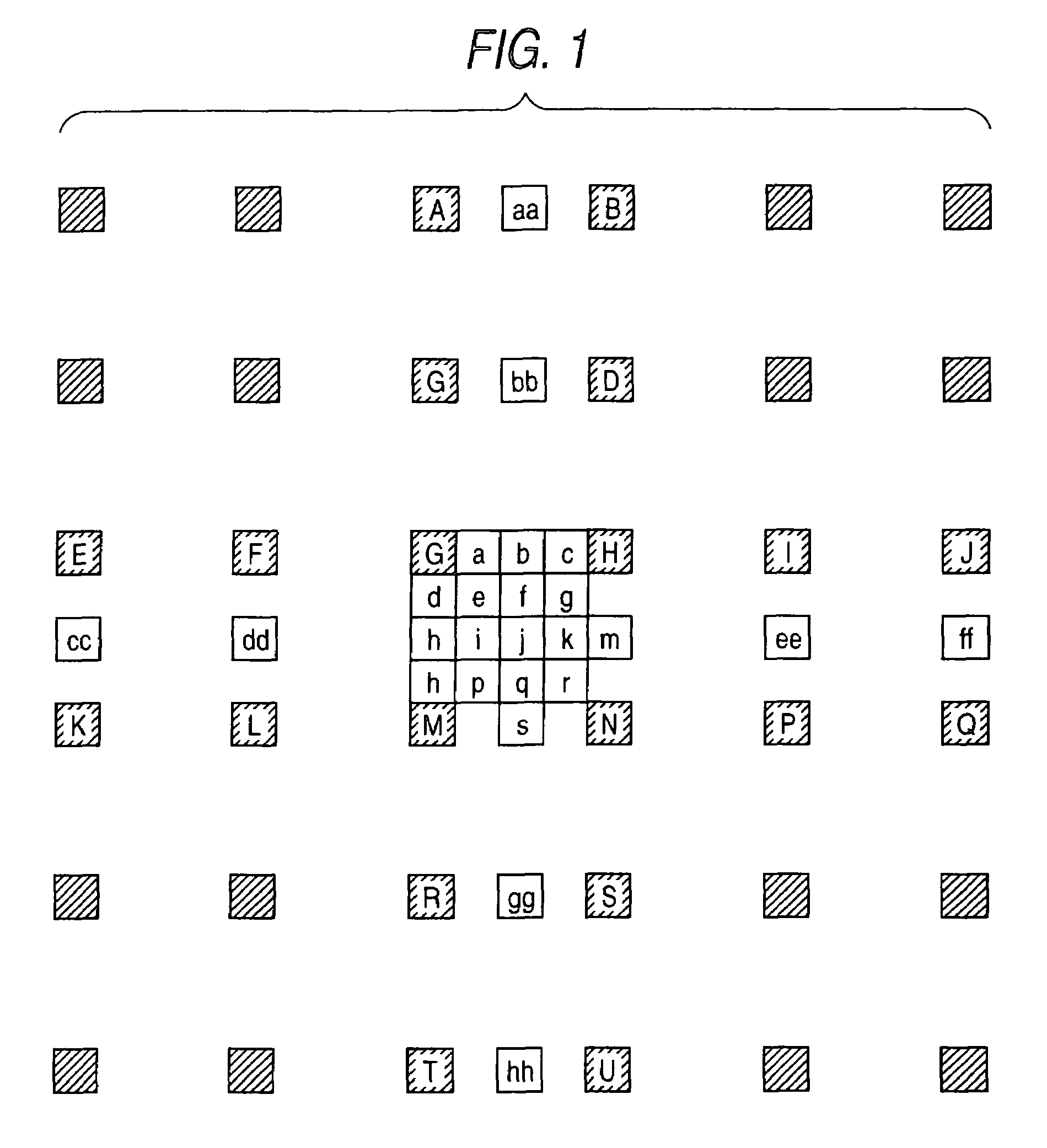
[0033]At the outset, explanation is made on the motion compensation as defined under the JVT coding scheme. Under the JVT coding scheme, motion compensation is available at ¼-pixel accuracy and at ⅛-pixel accuracy. The motion compensation process at ¼-pixel accuracy (interpolation process) is explained with reference to FIG. 1.

[0034]The JVT coding scheme uses a FIR (Finite Impulse Response) filter as a band limiting filter, to compensate for motion. As a filter coefficient for generating a pixel-based value (luminance signal) at ½-pixel accuracy, there is defined a 6-tap filter coefficients as follows.

{1,−5,20,20,−5,1}  (1)

[0035]Herein, as for the motion compensation (interpolation) for the pixel-based value b, h shown in FIG. 1, sum-of-products operation is made by the use of the filter coefficients of vector (1), according to the following equation.

b=(E−5F+20G+20H−5H+J)

h=(A−5C+20G+20M−5R+T)  (2)

Then, provided that the 8 bits of from “0” to “255” are consi...


PUM


Abstract

A process burden for code processing is reduced by the present system and method while possibly avoiding the lowering of image quality. When compensating for motion prediction by using a multi-reference frame while sequentially changing the pixel-based sizes of motion compensating blocks, a size-reduced block is generated depending upon a motion compensating block having the greatest pixel-based size to be taken as the uppermost layer among the pixel-based sizes. Thereafter, motion vector search ranges are determined respectively within the reference frame images, on the basis of a plurality of size-reduced reference images reduced in size respectively corresponding to the size-reduction ratios of the size-reduced blocks and the size-reduced blocks. Using the determined search range, an optimal motion vector is detected while sequentially changing the pixel-based sizes of the motion compensating blocks. This can detect a motion vector by only a limited search range within the reference frame image.

Description

BACKGROUND OF THE INVENTION[0001]1. Technical Field of the Invention[0002]This invention relates to a method and apparatus for compensating for motion prediction, which is suitably applicable to an image coding apparatus for transmitting, for example, motion picture signals over networks, such as the Internet.[0003]2. Description of the Related Art[0004]An image coding apparatus, conventionally, is configured to digitize a motion image signal supplied from an external source and then carries out code processing on it conforming to a predetermined image-coding scheme, thereby generating image-compressed information.[0005]The foregoing image-coding scheme is a known image coding scheme, called MPEG, standardized for the purpose of coding a general-use image by the Moving Picture Experts Group (MPEG) of ISO / IEC, and the image-coding scheme, called H.26* (i.e., H.261, H.262, . . . ), standardized aiming at coding a television-conference image.[0006]Meanwhile, the recent widespread use o...

Claims


Application Information

Patent Timeline
IPC IPC(8): G06K9/36G06K9/46H04N7/12G06T7/20H03M7/36H04N5/14H04N19/105H04N19/134H04N19/136H04N19/137H04N19/139H04N19/147H04N19/15H04N19/189H04N19/19H04N19/196H04N19/423H04N19/46H04N19/463H04N19/50H04N19/503H04N19/51H04N19/513H04N19/52H04N19/523H04N19/533H04N19/577H04N19/61H04N19/625H04N19/70H04N19/80H04N19/90
CPCG06T7/2026H04N19/57H04N19/523G06T2207/10016H04N5/145G06T7/238
Inventor SATO, KAZUSHIYAGASAKI, YOICHI
Owner SONY CORP
Features
  • Generate Ideas
  • Intellectual Property
  • Life Sciences
  • Materials
  • Tech Scout
  • Unparalleled Data Quality
  • Higher Quality Content
  • 60% Fewer Hallucinations
Learn More