Folding knife

a folding knife and folding technology, applied in the field of hand tools, can solve the problems of reducing the ease of storage and adding to the overall size of the folding knife, and achieve the effect of improving space utilization

Active Publication Date: 2010-03-16
LEATHERMAN TOOL GROUP
View PDF138 Cites 45 Cited by
  • Summary
  • Abstract
  • Description
  • Claims
  • Application Information

AI Technical Summary

Benefits of technology

[0006]The present invention addresses the previously mentioned shortcomings of the prior art and addresses the aforementioned desired features by providing a folding tool including improvements in space utilization such that a blade and an additional tool can share the same blade cavity in a coaxial or coplanar fashion, without causing the knife to be substantially longer than a single-blade knife of similar size and shape.
[0009]In yet another folding tool which is an embodiment of an aspect of the invention, an open-assist flipper is utilized to provide a novel method of opening the blade with one hand. The open-assist flipper is placed at the end of the knife and is completely, or almost completely, housed within the blade cavity. The open-assist flipper has a finger stud that sticks out toward the end of the knife in the gap between the two sides of the handle, and rotates around the same pivot axis as the knife blade, but the flipper is not mechanically linked to the knife blade. Rather, by rotating the finger stud around the pivot point, a flange, or lug, on the open-assist flipper body is made to contact the tang end of the blade at the blade kick, causing the blade to rotate out of the cavity. Since the open-assist flipper is not attached to the blade, it can be rotated back to its original position thereafter without causing the blade to be returned to the knife cavity. It also provides some controlled play such that if the lever gets snagged on an article of clothing or the like, it can rotate around the pivot point a certain amount without causing the blade to be deployed.

Problems solved by technology

As one might expect however, the addition of tools adds to the overall size of the folding knife, thereby decreasing the ease of storage, and potentially the desirability of carrying the knife in the first place.
Some of these mechanisms that exert stored potential energy on the blade and eject the blade from the storage cavity at high speed have been classified as illegal weapons and subsequently outlawed in some, but not all, jurisdictions.
This causes considerable problems for a person who may legally carry such a knife in his own jurisdiction, and therefore without thinking carries it into another jurisdiction where it has been outlawed.
Traditional placement of such mechanisms has been on the side of the blade or on the side of the handle, enlarging the tool and potentially providing a point where clothing or other items can be snagged or caught on the mechanism.

Method used


Image

  • Folding knife
  • Folding knife
  • Folding knife

Examples


Embodiment Construction

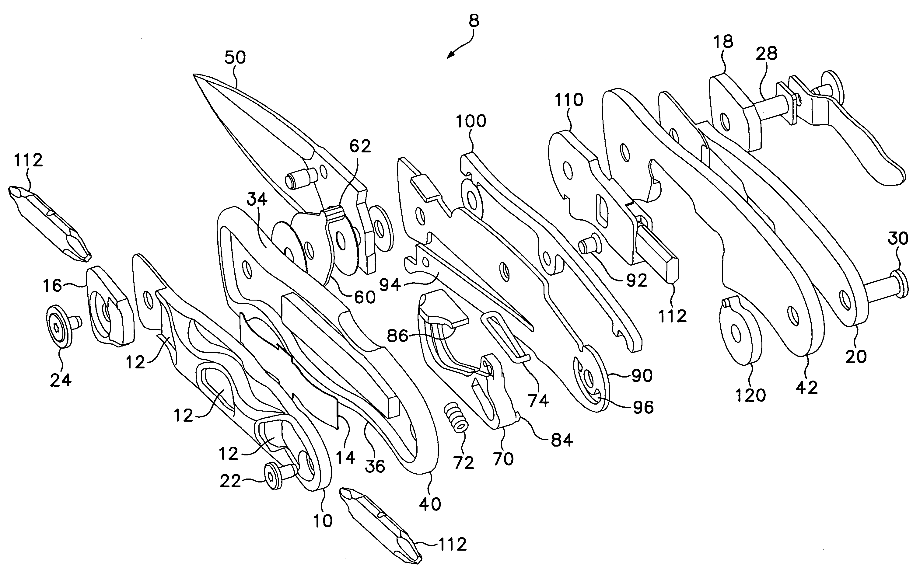
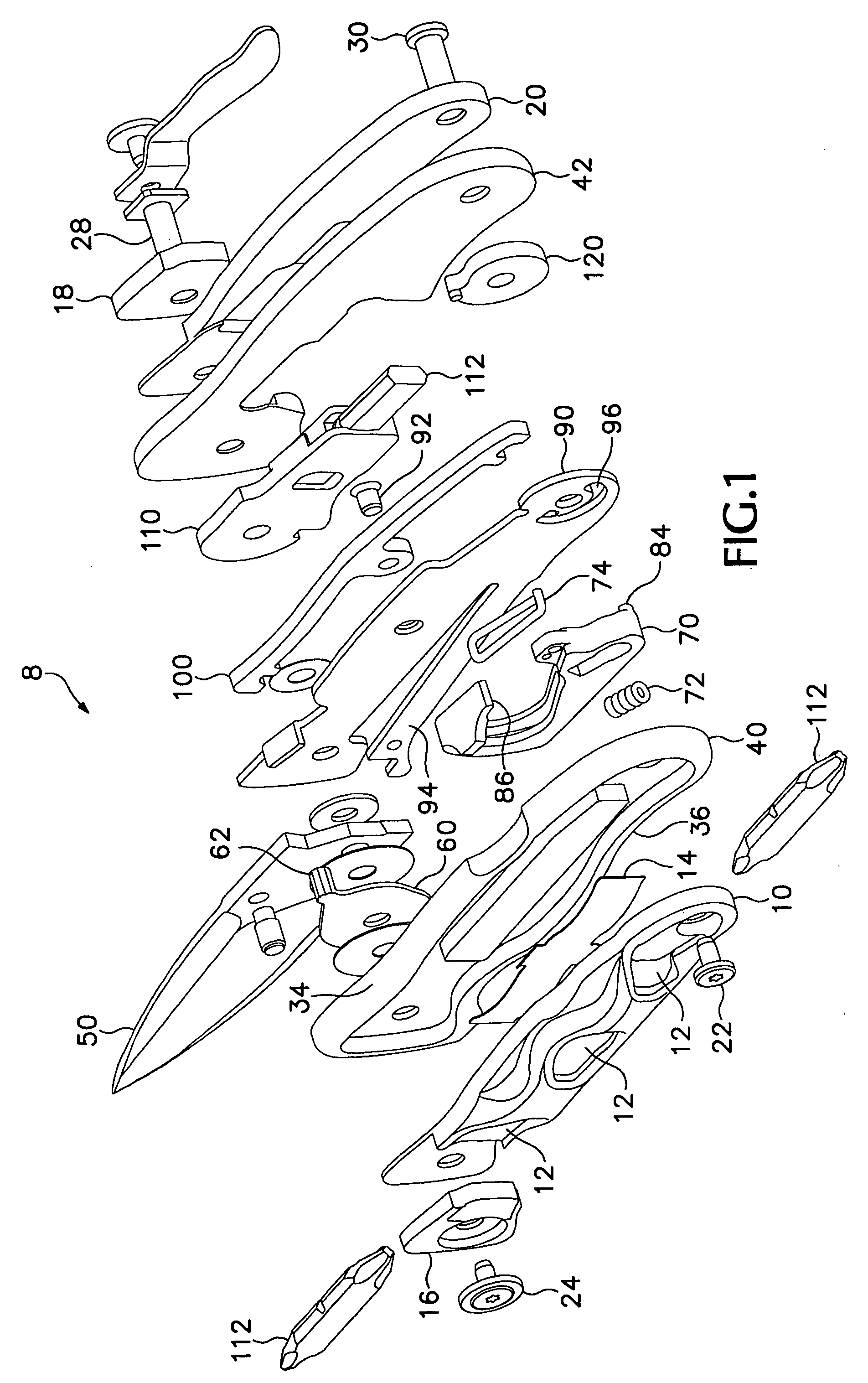
[0028]Referring now to the drawing figures, wherein like reference numerals represent like parts throughout the several figures, FIG. 1 shows an exploded view of a tool 8 including a folding knife of one embodiment of the present invention. The knife of this embodiment contains a pair of scales 10, 20 including the outer surfaces of the knife. Scale 10 defines a cavity within its body frame having outwardly facing openings, generally shown at 12, wherein one or more interchangeable bits 112 can be stored, yet can easily be extracted for use as needed. A bit retention spring 14 exerts a lateral force on the interchangeable bits 112 to secure them when being stored. The bit retention spring 14 is fitted into a recess (not shown) in scale 10, and is secured by frame 40, which provides resistance for the spring 14 to act upon when the tool 8 is assembled. Optionally, scale 10 and frame 40 can be manufactured as one part to serve the functions of both parts, as can be scale 20 and frame ...


PUM


Abstract

A folding hand tool with an open-assist mechanism that is not mechanically linked to a folding knife blade is disclosed. The open-assist mechanism is allowed to rotate around the same pivot used by the blade, and includes a lug that interacts with the kick of the blade when rotated. Because the open-assist mechanism is not mechanically linked to the blade, it has a range of free motion that promotes safety, and allows the mechanism to rotate into the blade cavity when the blade is extended. The folding knife also may have a carabiner that shares the blade cavity with the blade, with the blade nesting into the carabiner to save space, thereby giving the folding knife a smaller profile.

Description

FIELD OF THE INVENTION[0001]The present invention generally relates to hand tools, and in particular to tools wherein a cutting implement may be folded into a handle for improved storability and improved safety.BACKGROUND OF THE INVENTION[0002]Folding knives, or so-called pocket knives, have been around for over a hundred years and are well known in the art. Initially, folding knives were a single blade housed between two handle portions and rotatable around a pivot point such as a screw or rivet at one end of the handle. During use, the blade is rotated approximately 180 degrees such that the blade extends from the handle and the blade and handle share a common longitudinal plane. The handle and tang end of the blade come in contact to prevent the blade from over-rotating and to provide a solid cutting implement. For storage, the blade is rotated the opposite direction the same approximate 180 degrees, and stored in a cavity within the handle. With the blade stored, the overall len...

Claims


Application Information

Patent Timeline
Patent Type & Authority Patents(United States)
IPC IPC(8): B26B3/06B26B1/04
CPCB26B1/02B26B1/044B26B11/00
Inventor KNIGHT, NATHAN E.KLECKER, GLENN A.NENADIC, JOHN P.
Owner LEATHERMAN TOOL GROUP
Why Eureka
Try Eureka