Sound absorbent

a technology of absorbent and sound, which is applied in the field of sound absorbent, can solve the problems of irritating the respiratory passages of people, giving the sensation of dry air, and difficult to estimate, and achieves the effect of less cost and better absorption characteristics

Active Publication Date: 2010-03-16
DEAMP AS
View PDF21 Cites 21 Cited by
  • Summary
  • Abstract
  • Description
  • Claims
  • Application Information

AI Technical Summary

Benefits of technology

[0012]The object of the invention is to provide a new type of sound absorbent, which avoids the above-mentioned drawbacks of fibre based sound absorbents, and which simultaneously exhibits better absorption characteristics and is less costly to produce than many known sound absorbents based on microperforations. It is also an object of the invention to open new fields of use and to provide design-related advantages compared to known sound absorbents.

Problems solved by technology

The general problem with membrane absorbents is that the resistive component, which makes them function as an absorbent, is small, and moreover, is almost impossible to estimate.
There are various weaknesses with such fibre-based sound absorbing panels.
Such fibres are often made of melted glass or rock, and give the sensation of dry air and irritation of the respiratory passages of persons in such environments.
Furthermore, these fibres limit the appearance of such plates.
It is difficult to keep them clean as they require minimum use of moisture when cleaning, and problems related to mould and decay may arise, especially in rooms exposed to moisture, such as kitchens, indoor swimming pools and the like.
This movement results in viscous friction, by which the energy in the sound waves is converted to heat, whereby the sound waves are dampened.

Method used


Image

  • Sound absorbent
  • Sound absorbent
  • Sound absorbent

Examples


Embodiment Construction

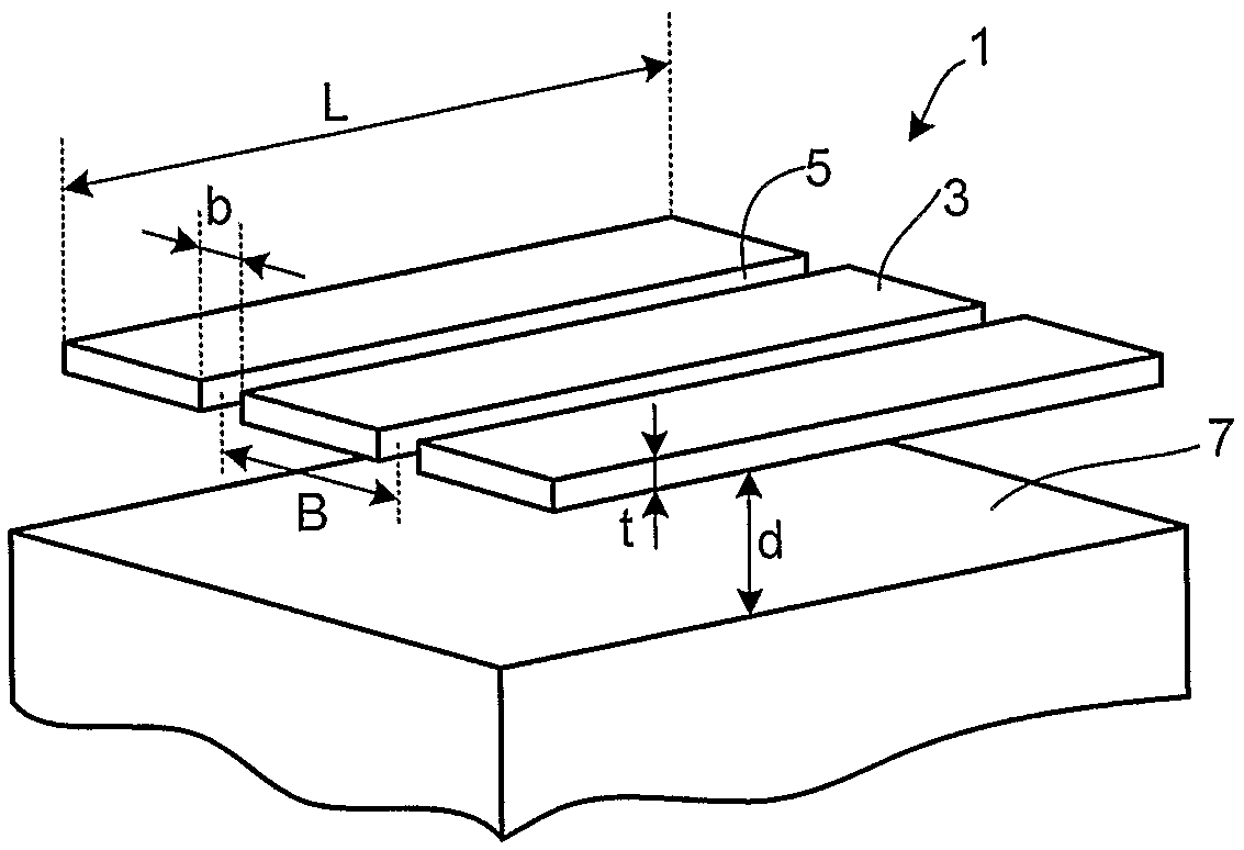
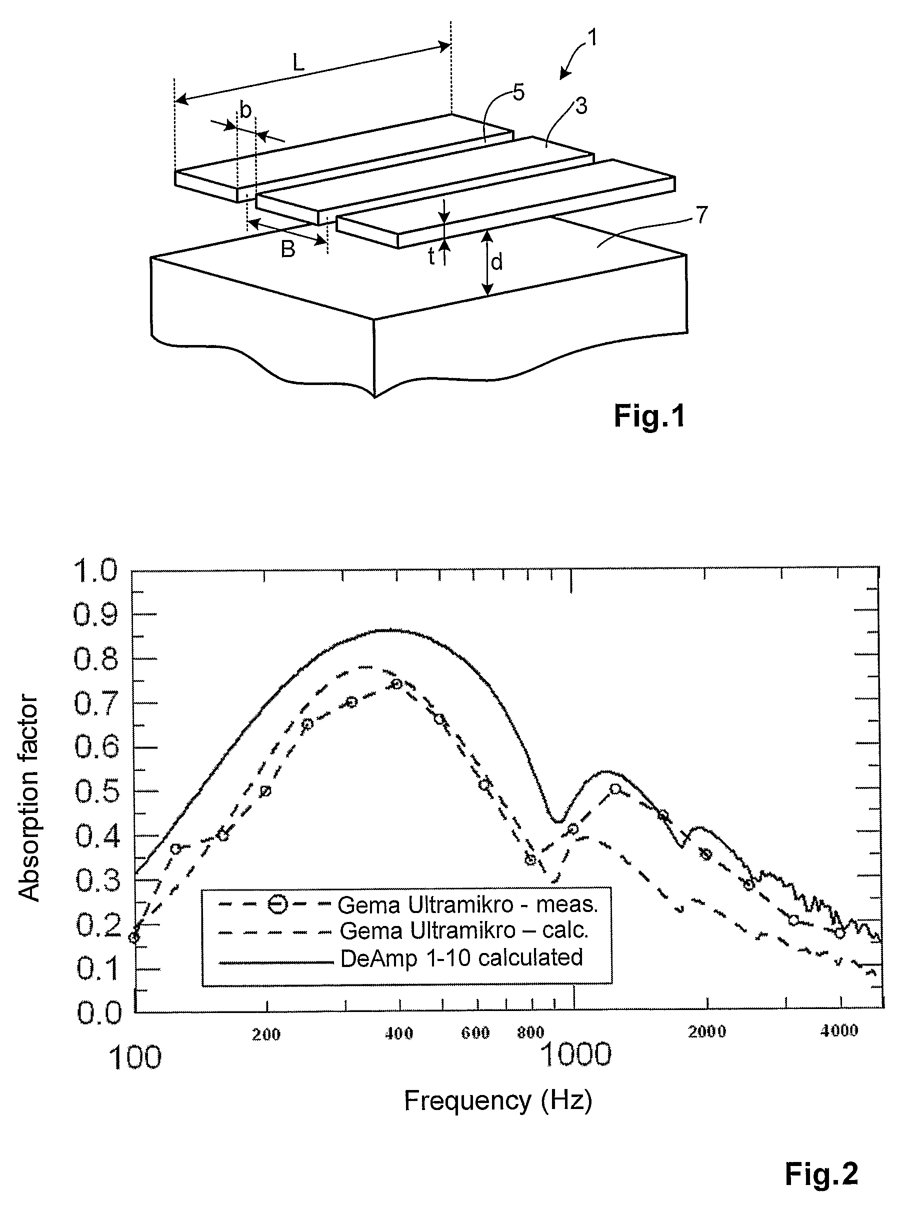
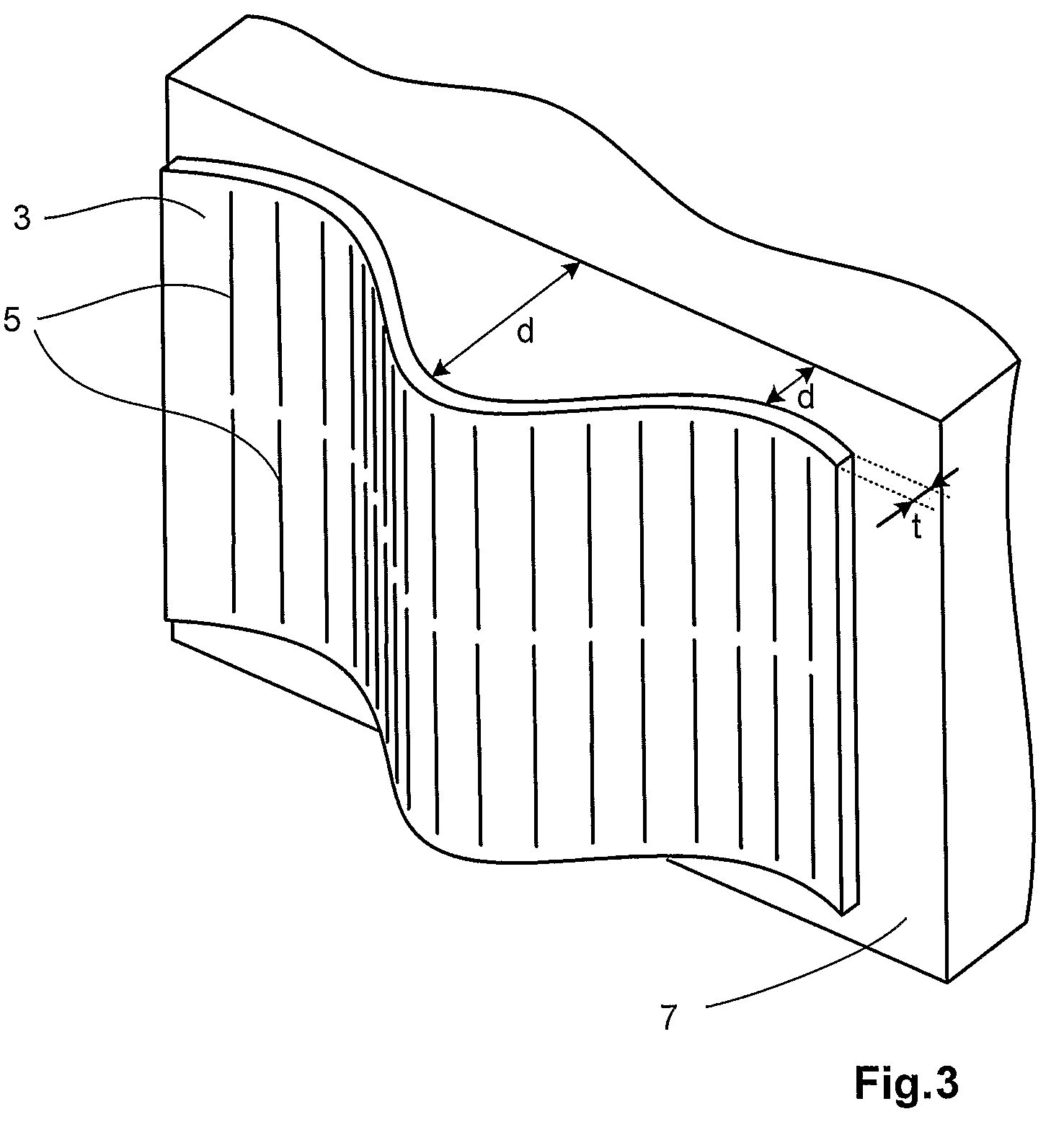
[0023]FIG. 1 is a principle drawing of a sound absorbent 1 according to the invention, comprising a panel element 3 with slits 5, arranged at a distance from a rear surface 7. Of the four parameters mentioned above, FIG. 1 indicates the width b of the slit, the distance B between the centre lines of adjacent slits 5, the thickness t of the panel element 3, and the distance d between the panel element 3 and the rear surface 7. The drawing in FIG. 1 only illustrates the principle of the design, and differs from a genuine embodiment of a sound absorbent according to the invention.

[0024]The slit width b is preferably less than 0.4 mm. Larger slit widths than this will yield poor absorption by friction of viscous flow. Advantageously, the slit width b is less than 0.3 mm. The distance between the panel element 3 and the rear surface 7 is preferably between 30 and 500 mm. This distance influences the frequency range for which the sound absorbent absorbs, as larger distances result in lowe...


PUM


Abstract

Sound absorbent (1) of a hard material, such as metal, glass, hard plastic or composites thereof, for absorption of acoustic waves by friction of viscous flow, essentially in the frequency range between 100 and 4000 Hz. The sound absorbent (1) comprises a panel element (3) with microslits (5) therethrough, said microslits (5) having a minimum slit width (b) of less than 0.45 mm. When in use, the panel element (3) is arranged with a distance to a rear surface.

Description

[0001]The invention relates to a sound absorbent for absorption of acoustic waves and especially to a planar shaped sound absorbent.BACKGROUND OF THE INVENTION[0002]In various types of indoor environments, such as office premises, receptions and reception halls, production premises, sports halls and indoor swimming pools, playgrounds and classrooms, it is desirable and also statutory according to regulations, to provide good acoustic conditions to the environment. Acoustic conditions can be best described by the reverberation, and to control this, sound absorbing elements are used, such as sound absorbing panels attached to walls, ceilings, and other surfaces.[0003]Sound absorbing panels as surfaces for attachment to indoor walls and ceilings come in types that use various physical effects for the absorption of sound. Firstly, there are so-called fibre absorbents. These comprise porous panels of mineral fibres (rock and glass wool), which dampen sound as the sound waves penetrate in...

Claims


Application Information

Patent Timeline
Patent Type & Authority Patents(United States)
IPC IPC(8): E04B1/82E04B1/74E04B1/84E04BE04B1/86G10K11/16
CPCE04B1/86G10K11/16E04B2001/8281E04B2001/8495E04C2/284E04F13/075E04B2001/8438E04F2290/041
Inventor VIGRAN, TOR ERIKPETERSEN, ODD
Owner DEAMP AS
Why Eureka
Try Eureka