Rotary piston engine

a rotary piston and engine technology, applied in the direction of rotary or oscillating piston engines, combustion engines, machines/engines, etc., can solve the problems of high production and maintenance costs, complex rotary piston engines, and high fuel consumption, and achieve greater fuel efficiency, less energy loss, and high torque

Inactive Publication Date: 2005-03-01
REED TOMMEY
View PDF12 Cites 11 Cited by
  • Summary
  • Abstract
  • Description
  • Claims
  • Application Information

AI Technical Summary

Benefits of technology

It is an additional object of the invention to provide a rotary engine that is high torque engine having greater fuel efficiency and less energy losses than rotary engines of the past.
It is another object of the invention to provide a simplified rotary engine that is less costly to produce and maintain while maximizing an amount of energy realized during combustion of fuel.

Problems solved by technology

The use of crank gears in a rotary piston engine is unnecessary since the piston performs a rotary motion during operation.
Because of the unique shape of the cylinder, it encounters sealing problems that result in high fuel consumption.
Most known rotary piston engines are complex and require high production and maintenance costs.

Method used


Image

  • Rotary piston engine
  • Rotary piston engine
  • Rotary piston engine

Examples


Embodiment Construction

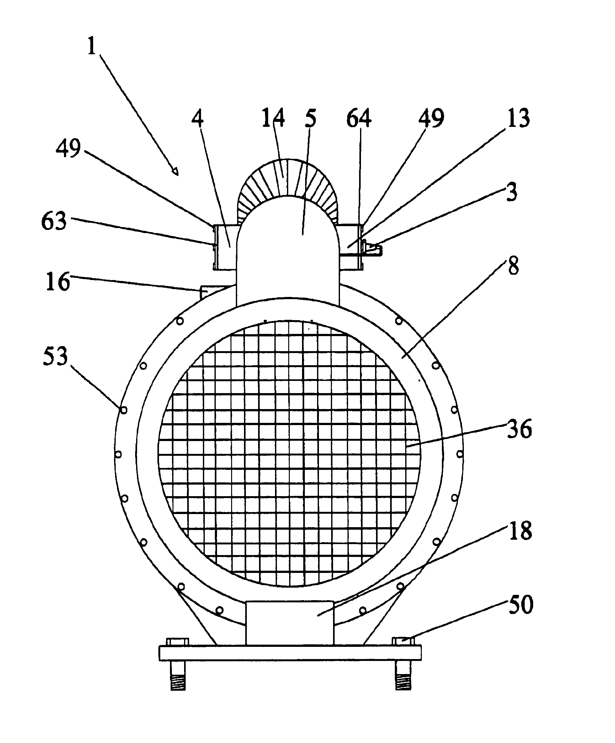
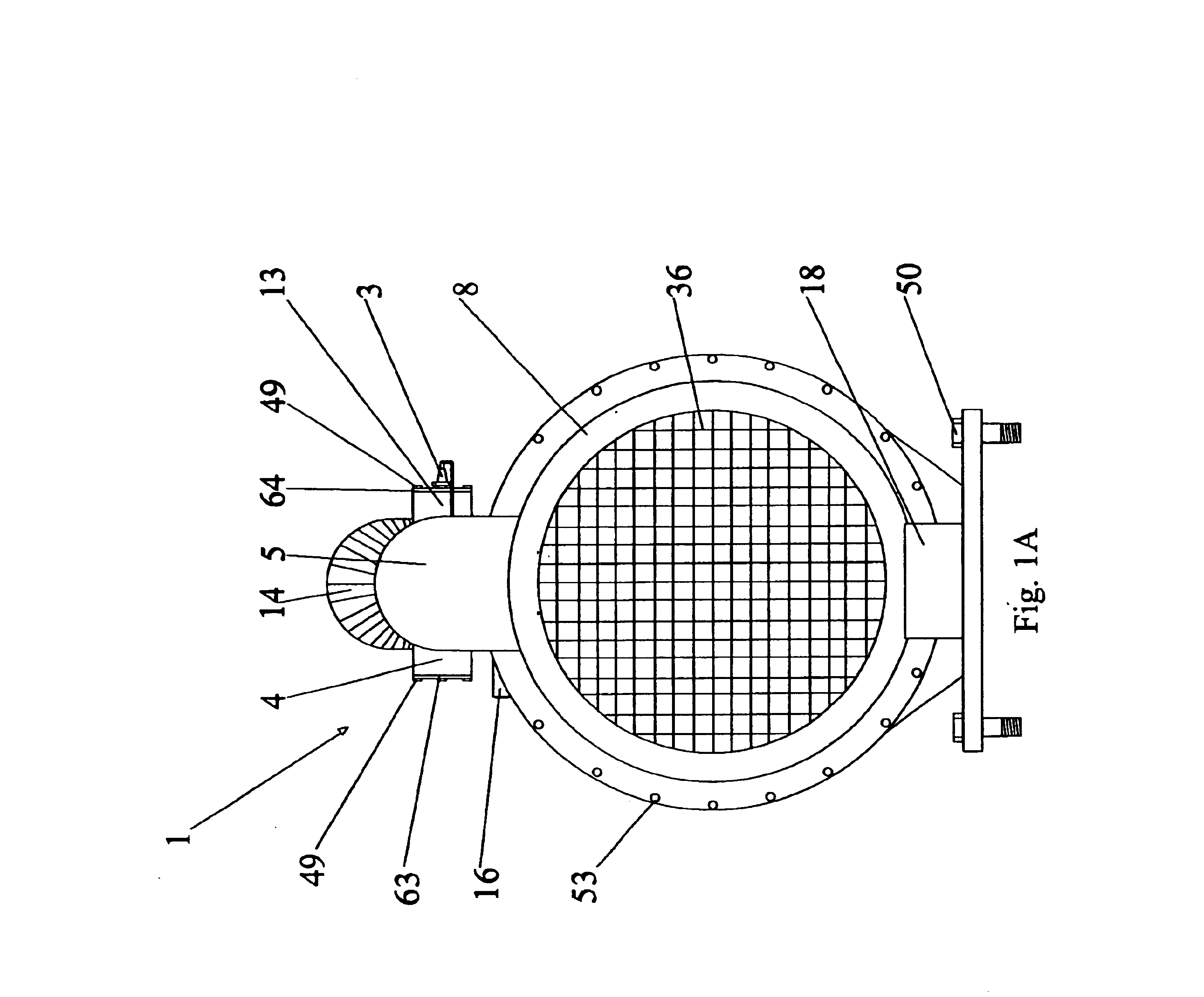
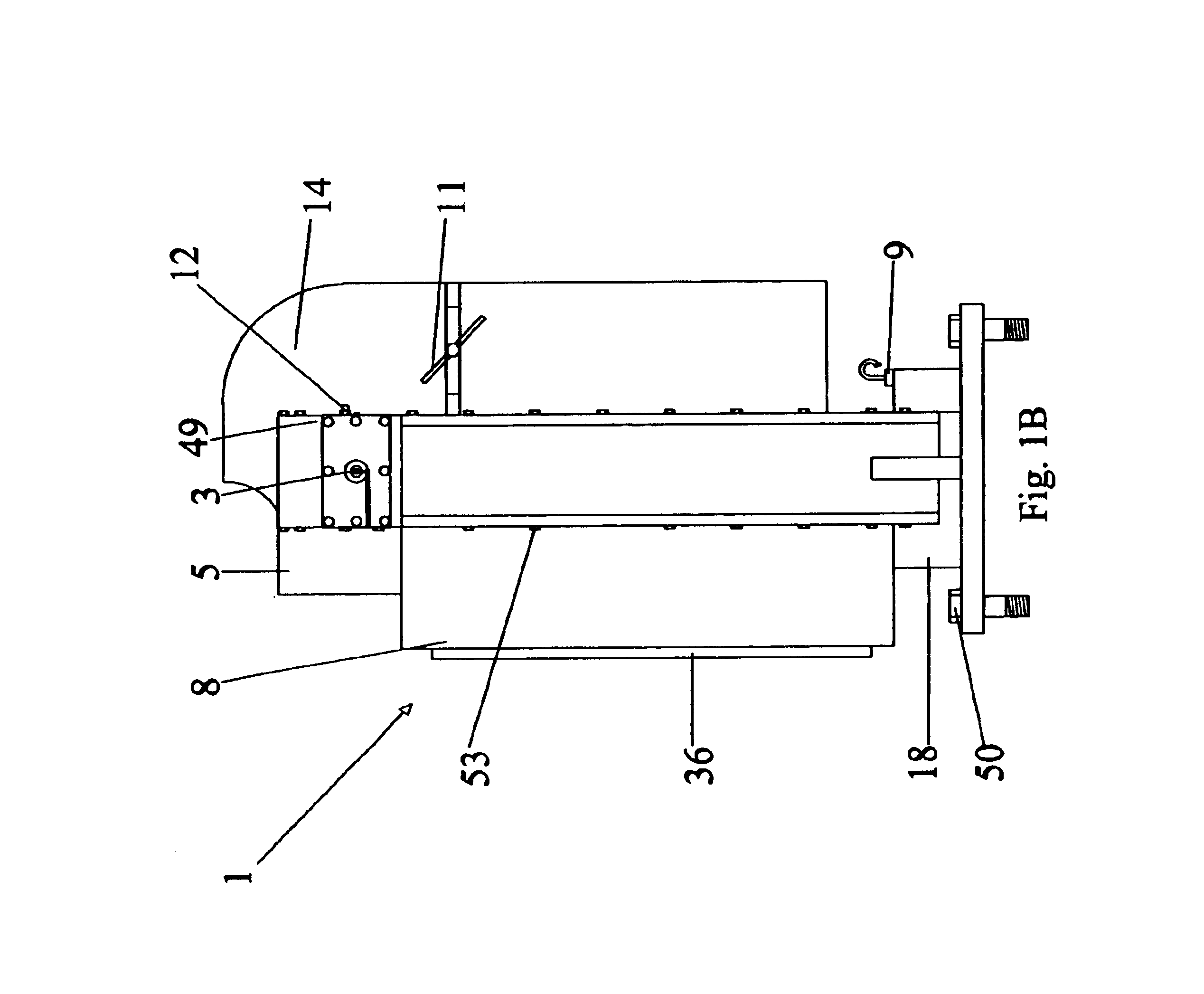
FIG. 1A shows the engine of the present invention. The engine 1 comprises an outer casing including a rotor case 8, a flywheel housing 36 and a valve cover 5. Each of these protects internal working parts by preventing foreign debris or materials from coming into contact with the internal workings of the engine. The various casings, housings and covers may be attached by known means such as bolts, screws, clips, fasteners or other such securing means.

In this embodiment, the engine 1 is shown as a gasoline type of engine. However, it may be noted that the engine may be modified to be driven with air, diesel, battery or steam. One of ordinary skill in the art can readily recognize that modifications may be undertaken to allow the engine to be driven by various propellants or forms of energy.

The upper portion of the engine comprises an air chamber 4 defined by head 63. Air flows into air chamber 4 through air intake vent 14 for use in the combustion process. Typically head 63 is constr...


PUM


Abstract

A rotary engine includes separate chambers for receiving pressurized air and fuel. An air chamber stories pressurized air that is routed into a combustion chamber to be mixed with fuel for combustion to drive a piston. The combustion chamber is forced open during a firing cycle to allow expanding gases into a piston chamber. A valve door serves as a base against which the expanding gases react to force a piston in a forward direction. The piston is coupled to a crank shaft which may in turn be coupled to a transmission or other power drive device to harness energy created by the turning crankshaft. A lifter includes a gear that rotates to raise and lower the valve door such that it moves towards and away from the crankshaft to optimize the amount of energy that is directed against the piston. Through series of multiplier gears, the amount of movement necessary to lift the door is minimal.

Description

There are no related patent applications.This patent application did not receive any federal research and development funding.BACKGROUND OF THE INVENTIONThe invention generally relates to a rotary piston engine. More particularly, the invention relates to a rotary piston engine that includes an air chamber for storing pressurized air that is routed into a separate combustion chamber for ignition purposes. The engine includes a housing that surrounds at least one rotor coupled to a piston for driving a shaft that may be coupled to a drive assembly for harnessing rotational energy produced by the rotor. A movable valve door provides a base against which expanding gases react to force the piston in a forward direction. The valve door is drawn away from the shaft to allow the piston to pass-by to complete a revolution.Internal combustion engines are typically referred to as either a reciprocating piston engine or a rotary piston engine. Reciprocating piston engines use crank gears to tr...

Claims


Application Information

Patent Timeline
Patent Type & Authority Patents(United States)
IPC IPC(8): F01C21/00F01C1/356F01C1/00F01C21/08F02B53/00F02B53/02
CPCF01C1/356F02B53/02F01C21/0827Y02T10/17Y02T10/12
Inventor REED, TOMMEY
Owner REED TOMMEY
Why Eureka
Try Eureka