
Non-axial actuable valve capable of retaining both high and low pressures

Inactive Publication Date: 2010-03-16
GENUINE INNOVATIONS
View PDF9 Cites 9 Cited by
  • Summary
  • Abstract
  • Description
  • Claims
  • Application Information

AI Technical Summary

Benefits of technology

[0023]Accordingly, several objects and advantages of the present invention will be presented in the following paragraphs followed by a thorough disclosure of each aspect in the accompanying embodiments in the DETAILED DESCRIPTION.
[0024]In light of the above-mentioned limitations, it is therefore an object of the present invention to teach non-axial actuable valve designs that will allow the valve embodiments to operate at both low and high operating pressures.
[0025]It is another object of the present invention to provide a non-axial actuable fluid pressure valve that self-resets to the closed position, when subjected to elevated operating pressure or no inle

Problems solved by technology

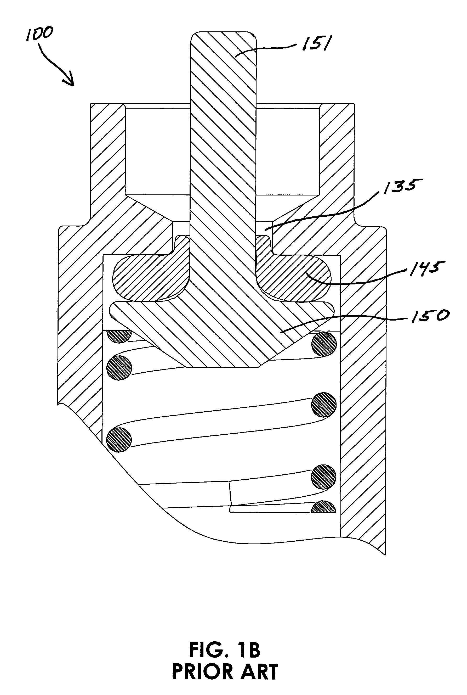
Illustrated in FIG. 1B PRIOR-ART, elevated inlet pressure makes valve actuation more difficult and will cause the elastomer seal to extrude as it excessively deforms under compression loading.
Also, illustrated in FIG. 1C PRIOR-ART, opening the standard non-axial actuable valve while retaining elevated pressure increases the chances that the elastomer seal will extrude right out of the valve body, in whole or in part, thus possibly not allowing the valve to actuate on, actuate off once actuated on, and / or cause elastomeric seal damage.
Therefore, the standard non-axial actuable valve works well in low pressure applications that only moderately deform the elastomeric seal and works poorly in elevated pressure applications that excessively deform the elastomeric seal.
Small amounts of contamination can quickly interfere with a hard seat thus not allowing the valve to completely close, causing a leak failure.
Either an additional elastomer bonding process must be practiced, thus increasing manufacturing costs, or a special shaped elastomer and / or valve seat(s) need to be made that are capable of capturing part of this seal in place thus maintain the seal into position.
Any of these bonding or securing methods do create an overall more complex non-axial actuable valve assembly also increasing cost.
In addition to higher cost and potential failure of the seal bond or containment method, exposure to chemicals, heat, or other potential failure modes such as high pressure can cause failure of the seal retaining means.
After much research, it became apparent that no manufacturers made such a valve that could handle inlet pressures operable to thousands of psig before failing and capable of opening through non-linear actuation while also sealing at 0 psig or substantially 0 psig.

Method used


Image

  • Non-axial actuable valve capable of retaining both high and low pressures
  • Non-axial actuable valve capable of retaining both high and low pressures
  • Non-axial actuable valve capable of retaining both high and low pressures

Examples


Embodiment Construction

[0051]The following paragraphs will detail several modes including the best mode of the present invention. The exemplary figures and description of the invention as it is exemplified in each figure is representative of the current invention and the scope of the invention disclosure is not intended to be limited by the exemplary teachings. One skilled in the pertinent art realizes that the embodiments to follow may reasonably be combined and / or modified without deviating from the intended spirit of the present invention. Like physical structure in different figures share the same identifying numbers.

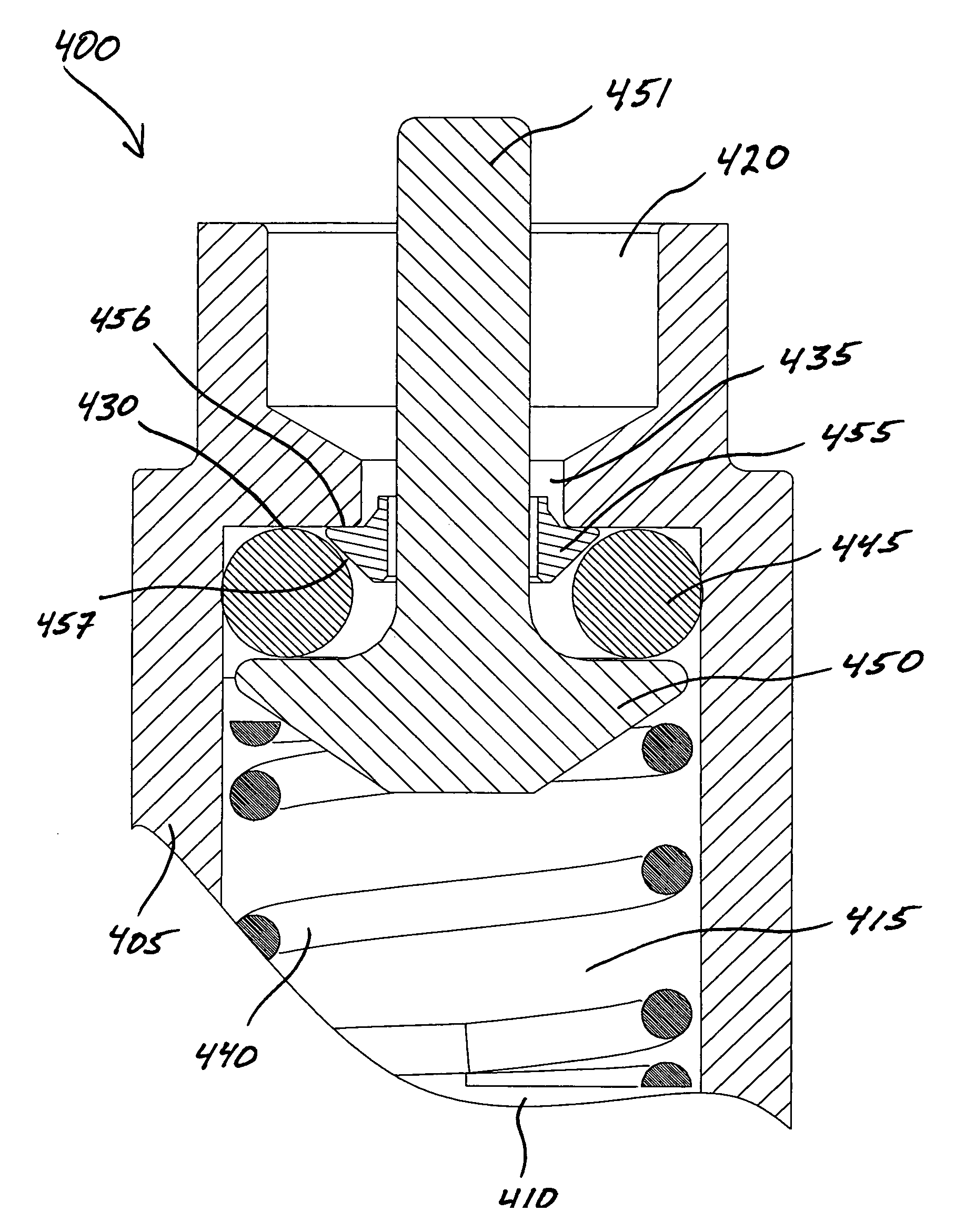
[0052]In accordance with an embodiment of the invention, FIG. 4A illustrates an exemplary non-axial actuable valve 400 subjected to little or no pressure, in accordance with the claimed invention. A valve body 405 is illustrated having a first end 410, a high pressure zone 415, and a second end 420. Valve body first end 410 is intentionally shown truncated. One skilled in the pertinent ar...


PUM


Abstract

The present invention relates to improved fluid valves actuable by a non-axial movement of an actuation stem. The non-linear actuable valves embodied in the present invention maintain pressure containment through a novel approach over the prior-art. The exemplary embodiments teach improved non-linear actuable valves that reduce the chances for seal extrusion, particularly at elevated retaining pressure, while keeping the component count low, and are capable of functioning under both high and low pressure.

Description

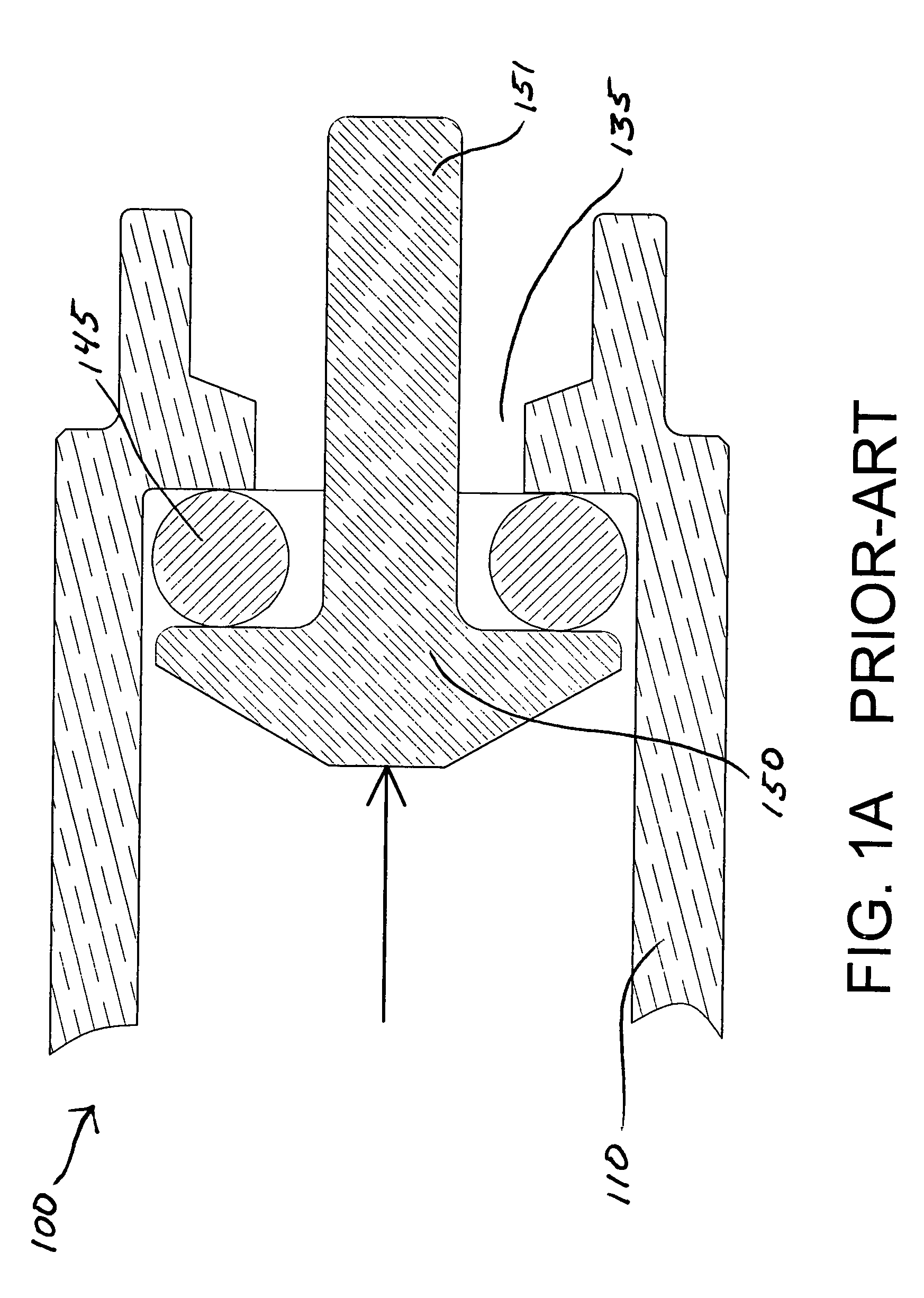
CROSS REFERENCE TO RELATED APPLICATIONS[0001]Not applicable.FEDERALLY SPONSORED RESEARCH[0002]Not applicable.REFERENCE TO A MICROFICHE APPENDIX[0003]Not applicable.FIELD OF THE INVENTION[0004]The present invention relates to improved fluid valves actuable by a non-axial movement of an actuation stem.BACKGROUND OF THE INVENTION[0005]Several species of prior-art valves are going to be discussed in the background, followed by a summary of why the present invention is novel and improved over the prior-art.[0006]Standard Style Non-Axial Actuable Valve: Summary[0007]FIG. 1A PRIOR-ART illustrates a non-axial actuable valve commonly used in low pressure pneumatic and hydraulic applications; for example used as a dog watering system that attaches to a hose bib on the outside of a home. A dog can drink a clean supply of water from the valve at will while not wasting excess water when not drinking from the valve. The dog watering valve typically utilizes a valve body comprising a bore that has...

Claims


Application Information

Patent Timeline
IPC IPC(8): F16K31/00
CPCF16K1/16F16K1/36F16K25/00A01K7/06
Inventor HOLLARS, ANTHONY SCOTTJANECEK, THOMAS F.
Owner GENUINE INNOVATIONS
Learn More