
Body framework construction

a body and frame technology, applied in the direction of roofs, transportation and packaging, vehicle arrangements, etc., can solve the problems of difficult to secure high strength, and achieve the effect of preventing the torsional deformation of the floor panel portion and increasing the strength of the body

Inactive Publication Date: 2010-03-16
MITSUBISHI MOTORS CORP +1
View PDF4 Cites 9 Cited by
  • Summary
  • Abstract
  • Description
  • Claims
  • Application Information

AI Technical Summary

Benefits of technology

[0006]It is therefore an object of the invention to provide a body framework construction which can prevent the torsional deformation of the floor panel portion and which can increase the strength of the body.
[0011]wherein the gusset is deformed more easily than the backbone relative to a force from a front.

Problems solved by technology

In the vehicle body framework construction of the related art that has been described above, however, there have been the following problems inherent therein.
Namely, since the floor panel is made up of the single plate member, it is easily subject to torsional deformation, and since the configuration is adopted in which the backbone intended to increase the strength is not directly joined to the rear seat cross member and is provided on only part of the floor panel, it has been difficult to secure high strength.

Method used


Image

  • Body framework construction
  • Body framework construction
  • Body framework construction

Examples


Embodiment Construction

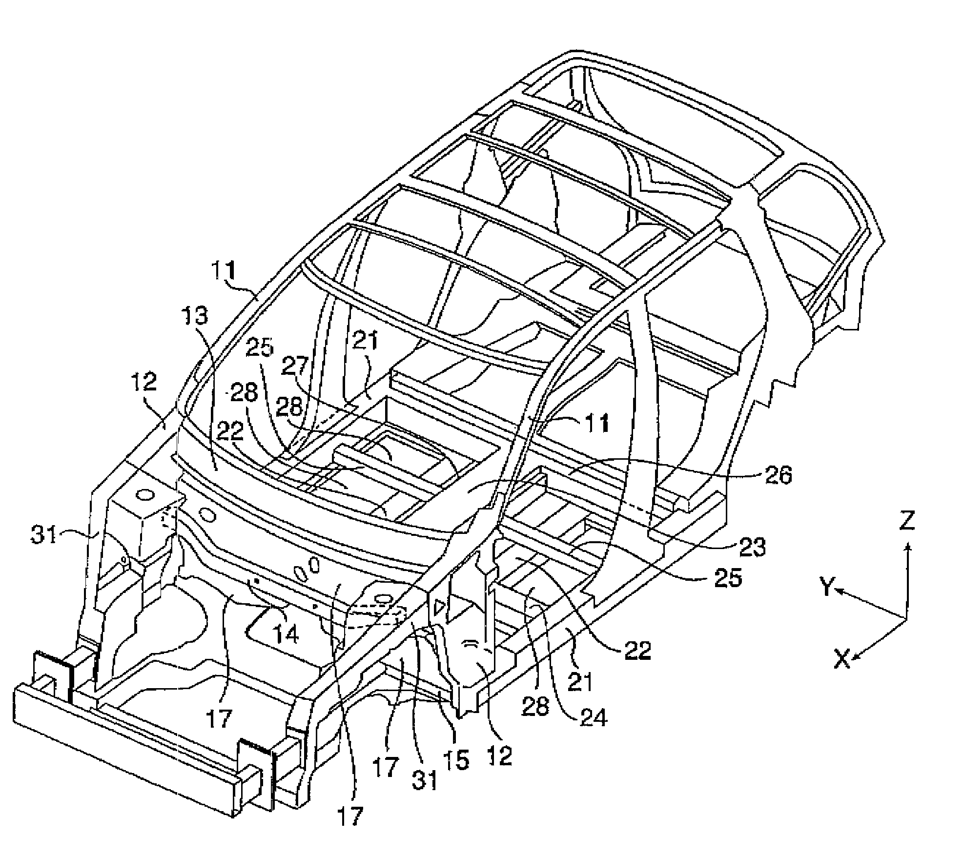
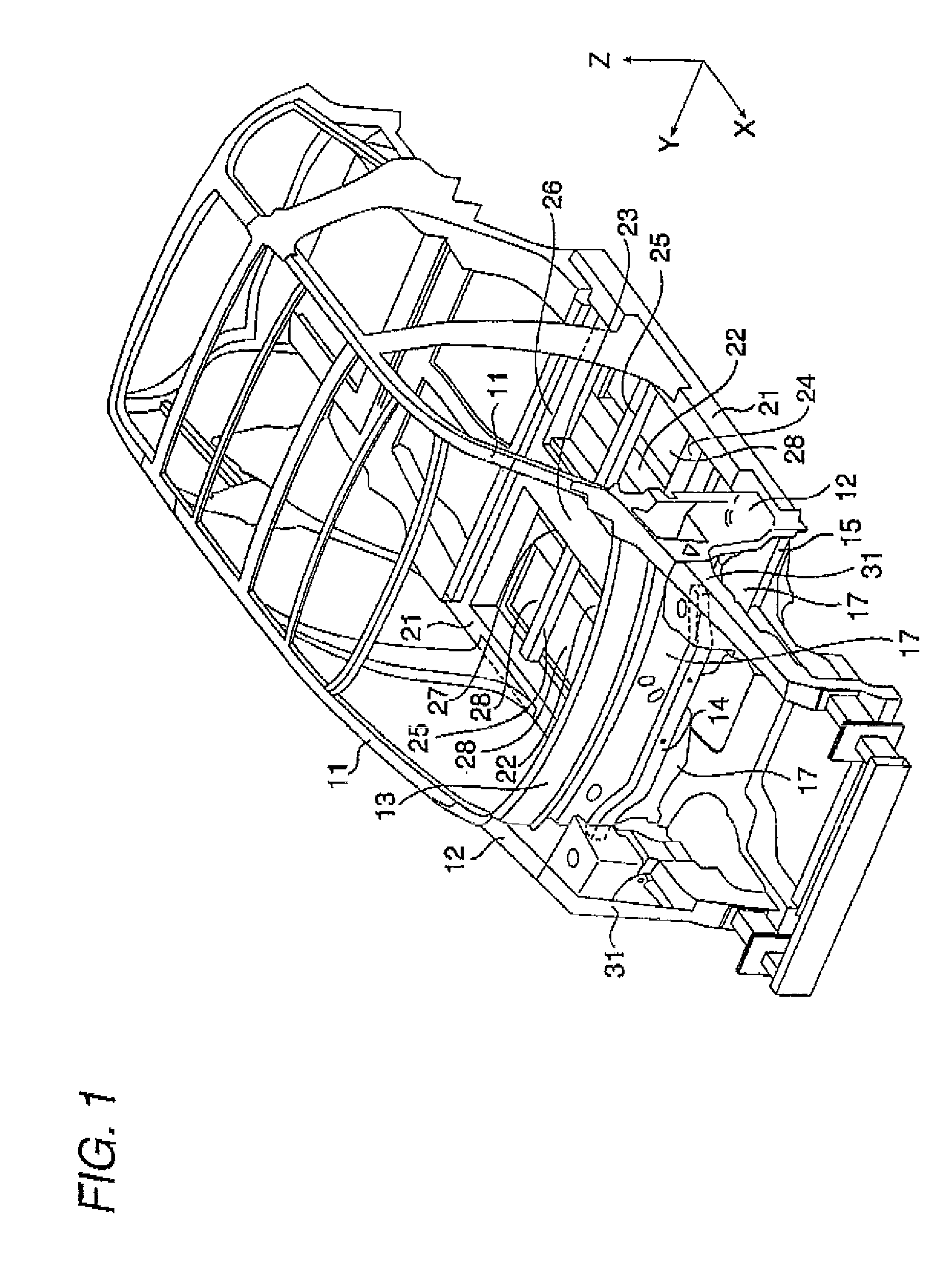
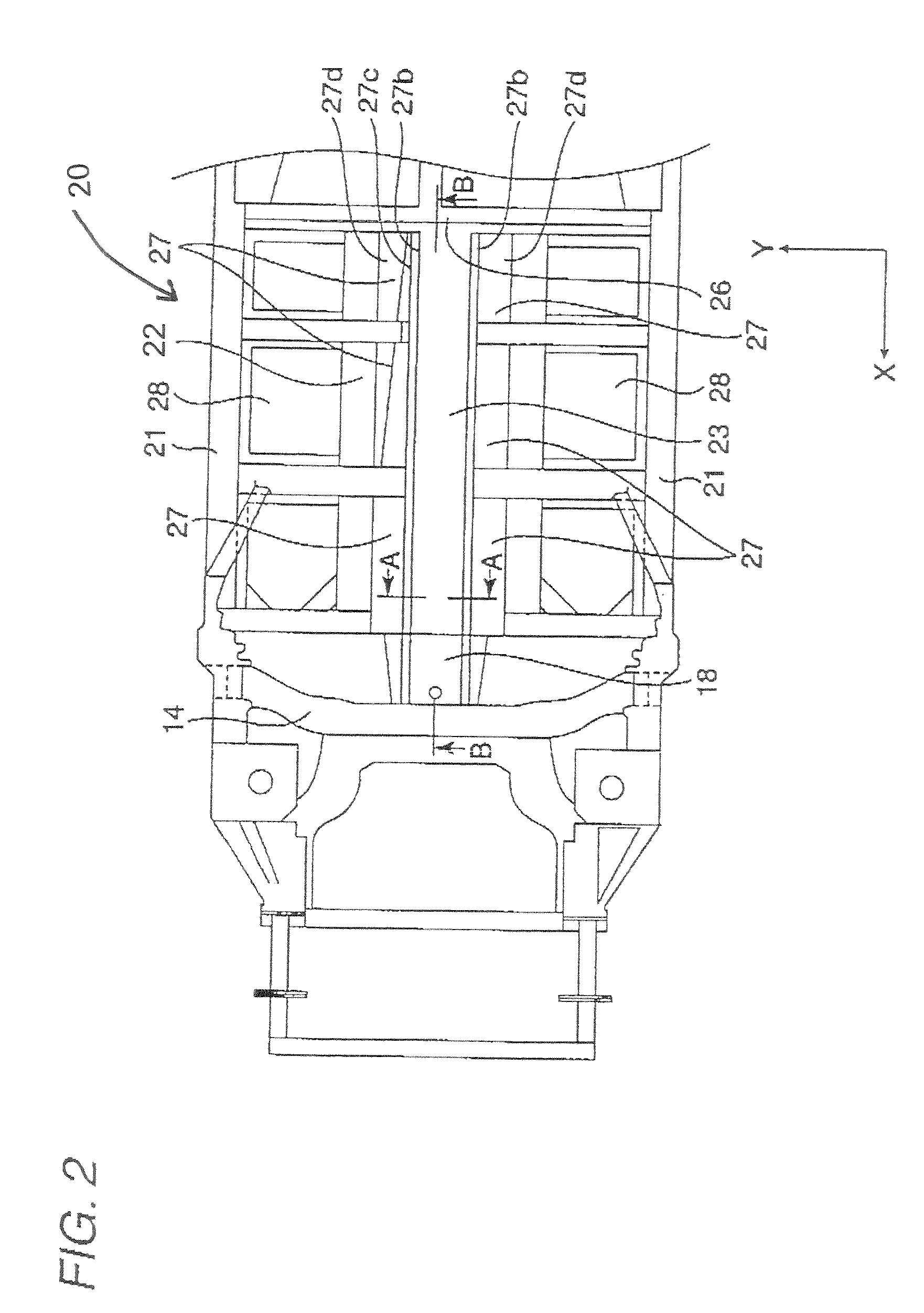
[0020]Hereinafter, a body framework construction according to a first embodiment of the invention will be described by reference to FIGS. 1 to 5. Note that front (front side), rear (rear side) and left to right width or transverse directions are defined based on a traveling direction of a motor vehicle, and a direction which is directed towards a transverse center of the motor vehicle is defined as an inward direction (inside) whereas a direction expanding from the center of the motor vehicle towards the transverse direction as an outward direction (outside). A direction in which gravity acts is defined as a downward direction (lower side), and a direction opposite to the direction in which gravity acts as an upward direction (upper side). In the figures, arrows X, Y and Z denote three directions which are at right angles to one another, the arrow X denoting the front of a body, the arrow Y denoting a left-hand side of the body as viewed in the transverse direction, the arrow Z deno...


PUM


Abstract

A body framework construction, includes: a rear seat cross member, extending in a transverse direction of a vehicle, in a rear part of a body in a lower part of a passenger compartment; a dash cross member upper, extending in the transverse direction, in a front part of the passenger compartment; and a backbone, configured into a thin, long shape having a closed cross section, and extending in a longitudinal direction of the vehicle. A front end portion of the backbone is connected to the dash cross member upper via a gusset, and a rear end portion of the backbone is joined to the rear seat cross member. The gusset is deformed more easily than the backbone relative to a force from a front.

Description

BACKGROUND OF THE INVENTION[0001]1. Field of the Invention[0002]The present invention relates to a body framework construction which is disposed at a lower part of a passenger compartment of a motor vehicle.[0003]2. Description of the Related Art[0004]As a framework construction of the related art which supports a lower part of a passenger compartment of a motor vehicle, there is a framework construction in which a front end portion of a floor panel which makes up a floor portion of the passenger compartment is joined to a dash panel disposed between an engine compartment and the passenger compartment and a rear end portion is joined to a rear seat cross member which extends in a transverse direction of the vehicle in the rear of a body. A tunnel portion where an exhaust pipe and a drive shaft pass are provided to pass through to the rear of the body is formed in a transversely central portion of a floor panel like the one described above. The tunnel portion has a U-shaped cross sec...

Claims


Application Information

Patent Timeline
Patent Type & Authority Patents(United States)
IPC IPC(8): B62D25/00
CPCB62D25/20B62D25/2018
Inventor NAKAMURA, TAKUONAKAGAWA, HAYAMITAKASHINA, KATSUHIKOKANO, HIROAKIYANASE, JUNICHISEINO, HIROYUKIITO, HIDEKIYANAGIMOTO, SATOSHI
Owner MITSUBISHI MOTORS CORP
Learn More