Ophthalmologic photographing apparatus

a photographing apparatus and ophthalmology technology, applied in the field of ophthalmologic photographing apparatus, can solve the problems of complicated optical system, increased size, limited emission wavelength band and light emitted from led light emitting elements, etc., and achieve the effect of simple structure and efficient and uniform illumi

Inactive Publication Date: 2010-03-16
CANON KK
View PDF9 Cites 38 Cited by
  • Summary
  • Abstract
  • Description
  • Claims
  • Application Information

AI Technical Summary

Benefits of technology

[0009]The present invention is directed to an ophthalmologic photographing apparatus capable of efficiently and uniformly illuminating a fundus of a subject's eye with a simple structure using a single light source serving as both an observation light source and a photographing light source.

Problems solved by technology

However, the fundus camera using two types of filters, i.e., a visible cut-off filter and an infrared light cut-off filter, has a drawback in that the optical system is complicated and is increased in size.
However, the emission wavelength band and the intensity of light emitted from an LED light emitting element are limited.
Thus, it is difficult to configure a fundus camera to use a light source for both observation and photographing and to switch between visible light and infrared light using wavelength selecting filters, as discussed in Japanese Patent No. 3,004,276.
Consequently, it is difficult to reduce the system in size.

Method used


Image

  • Ophthalmologic photographing apparatus
  • Ophthalmologic photographing apparatus
  • Ophthalmologic photographing apparatus

Examples


first exemplary embodiment

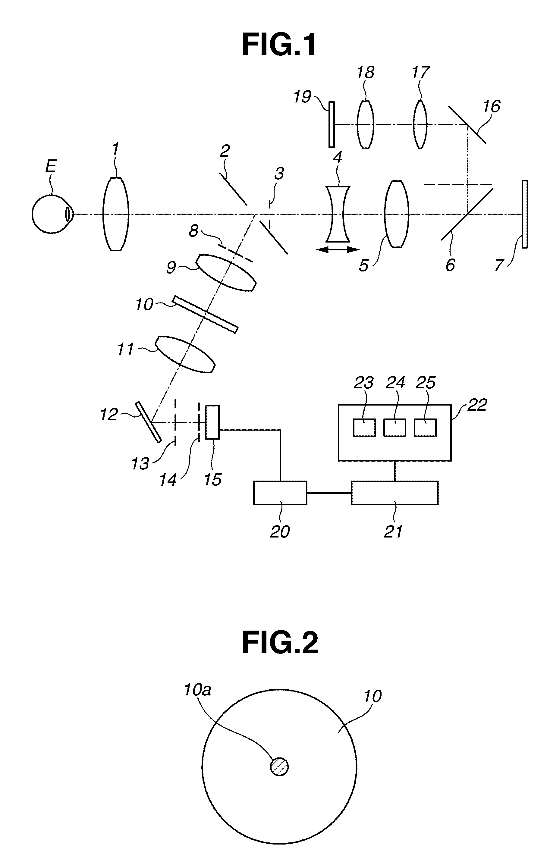
[0028]FIG. 1 illustrates a configuration of a non-mydriatic fundus camera according to a first exemplary embodiment of the present invention. An objective lens 1, a perforated mirror 2, a photographic aperture stop 3, a focus lens 4 that is movable along an optical axis, an imaging lens 5, a moveable (flip-up) mirror 6, and an imaging unit 7 are sequentially arranged in front of a subject's eye E and constitute a photographing optical system.

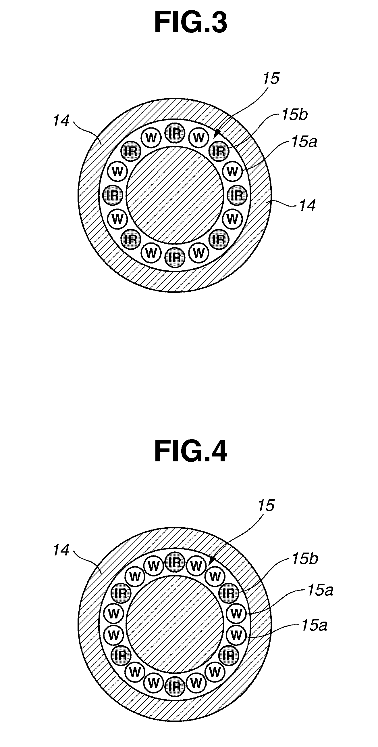
[0029]A cornea stop 8, a relay lens 9, a black point plate 10, a further relay lens 11, and a mirror 12 configured to reflect illumination light are sequentially disposed in a light incident direction of the perforated mirror 2. The cornea stop 8 has a ring-shaped opening for separating observation illumination light from photographing illumination light so as to prevent the incidence of harmful reflection light on the photographic aperture stop 3, which is obtained by reflecting illumination light and comes from a cornea of the subject's eye E....

second exemplary embodiment

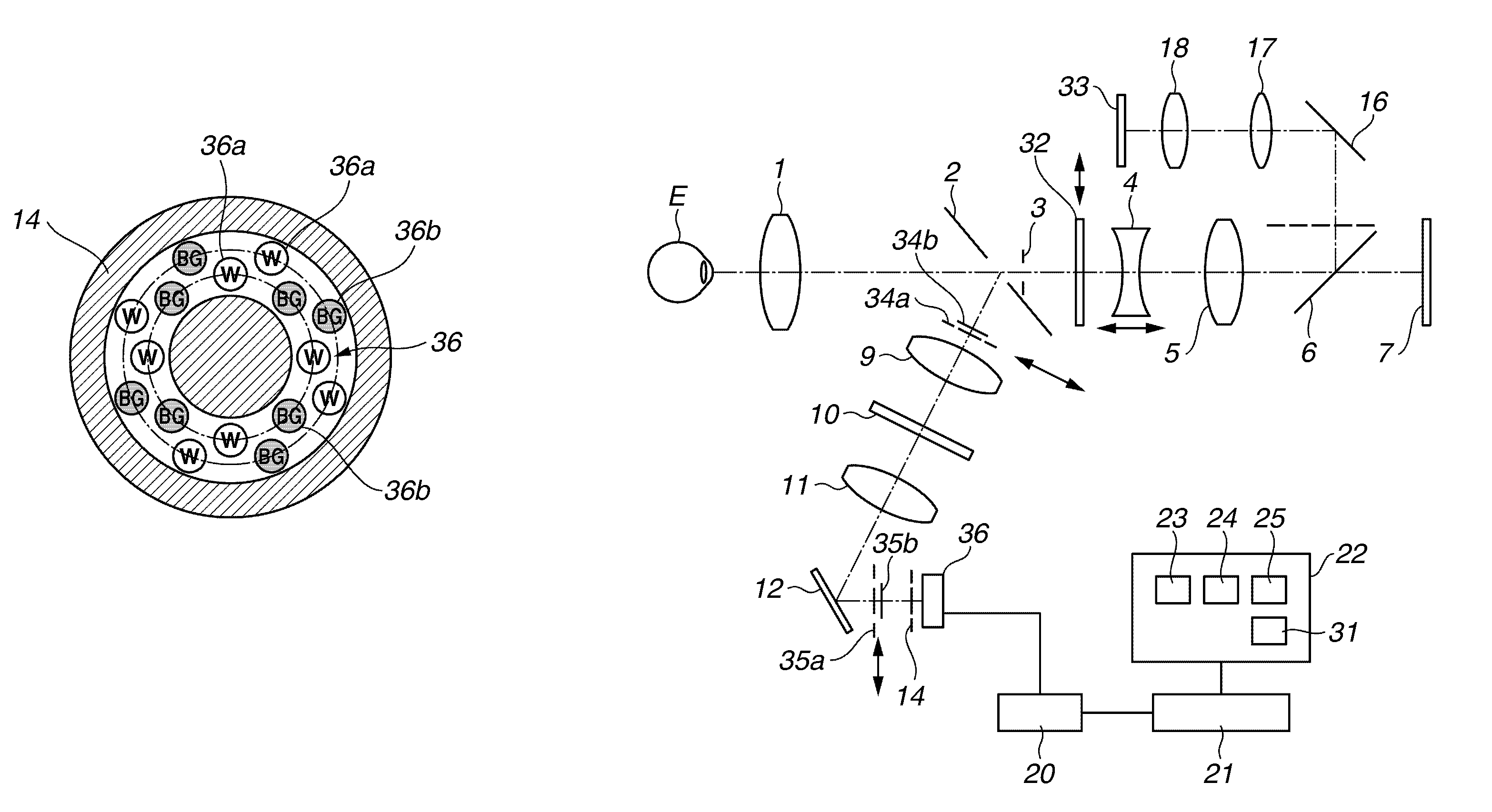
[0044]FIG. 6 illustrates a configuration of a fluorescein fundus camera for diagnosis of blood vessels on a fundus of a subject's eye according to a second exemplary embodiment of the present invention. In FIG. 6, a member that is similar to an associated member of the non-mydriatic fundus camera according to the first exemplary embodiment is designated with the same reference numeral as that designating the associated member of the non-mydriatic fundus camera.

[0045]The fluorescein fundus camera according to the second exemplary embodiment of the present invention includes a photographing mode selector switch 31 provided on an operation panel 22 so as to select a photographing mode from among a fluorescent photographing mode and a color photographing mode. A barrier filter 32 having a transmission band of wavelengths ranging from 530 nm to 630 nm is provided between a photographic stop 3 and a focus lens 4 to be able to be inserted into and removed from the optical path of the illum...


PUM


Abstract

An ophthalmologic photographing apparatus includes a light source having two or more types of light-emitting-diode (LED) light emitting elements configured to emit light of different wavelengths, an illumination optical system configured to illuminate a fundus of a subject's eye with light emitted by the light source, an imaging optical system configured to form a fundus image from light reflected from the fundus of the subject's eye illuminated by the illumination optical system, and a control unit configured to control the light source to emit light of different wavelengths, with which the fundus of the subject's eye is illuminated, between when the formed fundus image is observed and when the formed fundus image is captured as a still image.

Description

BACKGROUND OF THE INVENTION[0001]1. Field of the Invention[0002]The present invention relates to an ophthalmologic photographing apparatus for photographing a fundus of a subject's eye.[0003]2. Description of the Related Art[0004]Fundus cameras are roughly classified into non-mydriatic fundus cameras and mydriatic fundus cameras. The non-mydriatic fundus camera captures an image of a fundus of a subject's eye with visible light after the subject's eye is observed with near-infrared light. The mydriatic fundus camera captures an image of a fundus of a subject's eye with visible light after the subject's eye, whose pupil is dilated with a mydriatic, is observed with visible light.[0005]In the mydriatic fundus camera, a visible light cut-off filter is inserted in front of a halogen light source in order to prevent a pupil of a subject's eye from being narrowed with observation light. Consequently, only an infrared component of light emitted from the halogen light source is transmitted ...

Claims


Application Information

Patent Timeline
Patent Type & Authority Patents(United States)
IPC IPC(8): A61B3/14
CPCA61B3/14A61B3/12
Inventor SHIMIZU, SATOSHI
Owner CANON KK
Why Eureka
Try Eureka