
Backlight module and an optical slice unit support device thereof

a technology of backlight module and support device, which is applied in the direction of machine supports, lighting and heating apparatus, instruments, etc., can solve the problems of damage to the light source module below, and the light source module is susceptible to structural damage, and achieves the effect of higher structural stability

Active Publication Date: 2010-03-16
AU OPTRONICS CORP
View PDF7 Cites 1 Cited by
  • Summary
  • Abstract
  • Description
  • Claims
  • Application Information

AI Technical Summary

Benefits of technology

[0008]It is an object of the present invention to provide a backlight module having a higher structural stability.
[0009]It is another object of the present invention to provide a backlight module having a simple and easy assembly process.
[0011]It is yet another object of the present invention to provide a support device used in a backlight module having a higher bearing capacity.

Problems solved by technology

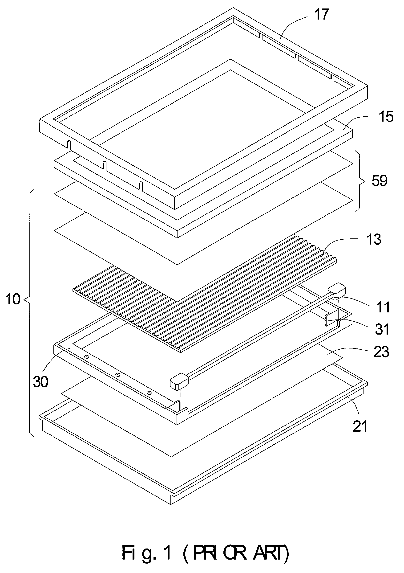
However, when the stop plate 31 formed integratedly with the frame 30 and being plastic made bears a light guide plate 13 having larger dimensions, it is susceptible to structural damage due to insufficient bearing capacity, and further damages the light source module below.

Method used


Image

  • Backlight module and an optical slice unit support device thereof
  • Backlight module and an optical slice unit support device thereof
  • Backlight module and an optical slice unit support device thereof

Examples


Embodiment Construction

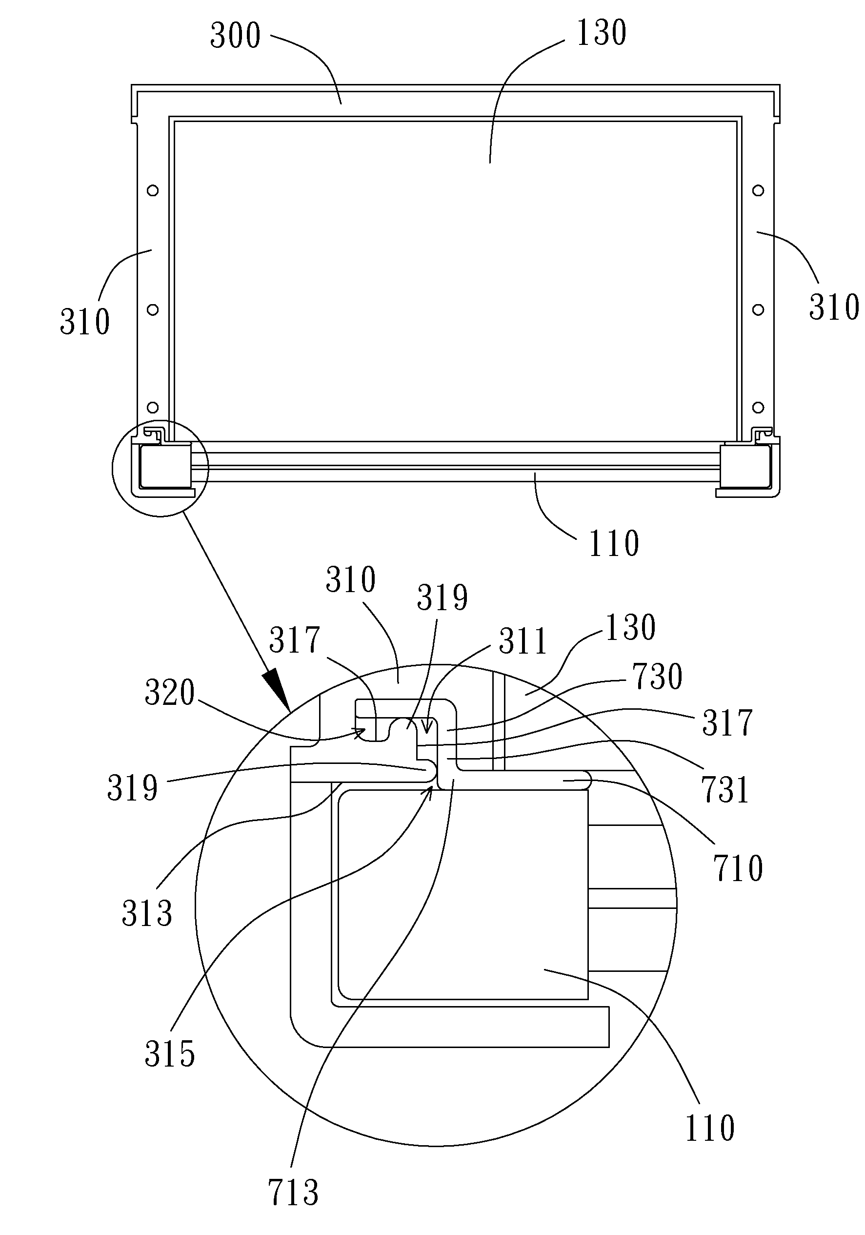
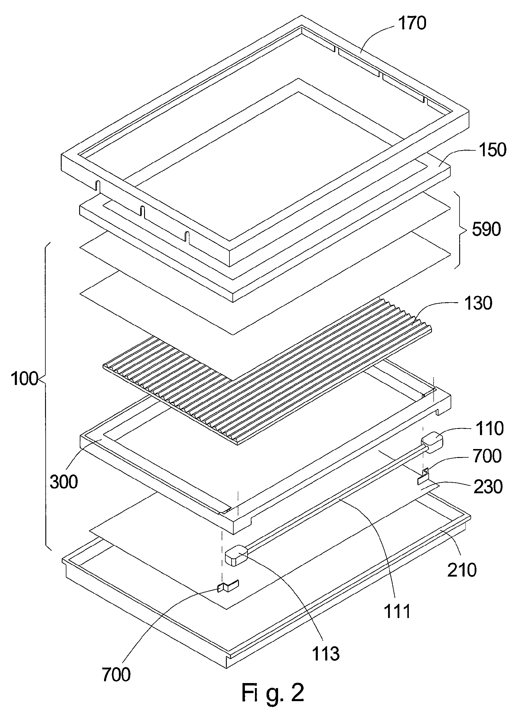
[0026]The present invention provides a backlight module and a support device for an optical slice unit / a sheet-form optical element contained within the backlight module. For the preferred embodiment, the backlight module is used in a liquid crystal display (LCD) device. However, in other embodiments, the backlight module may be used in computer keyboards, cell phone buttons, billboards and other devices requiring flat light sources. Specifically speaking, the present invention further includes a LCD device using the backlight module. In the preferred embodiment, the LCD device in accordance with the present invention includes a color LCD device. However, in other embodiments, the LCD device according to the present invention may include a monochromatic LCD device. The above LCD device refers generally to display devices using liquid crystal (LC) panels, including LC monitors of household LCTVs, personal computers and laptops, and LC display screens of cell phones and digital camera...


PUM


Abstract

The present invention provides a backlight module and a support device for a sheet-form optical element contained within the backlight module. The backlight module mainly includes a frame, a support device and the sheet-form optical element disposed within the frame. The support device includes a support portion and a positioning portion. The support portion has a support end and a connection end. The support end extends into the space within the frame, and supports the bottom end of the sheet-form optical element. The positioning portion has a first end, a second end and a bend portion connecting the first end with the second end. The first end connects to the connection end of the support portion, and an included angle exists between the first end and the support portion. The positioning portion of the support device is inset in the frame to provide a support force for the support portion.

Description

BACKGROUND OF THE INVENTION[0001]1. Field of the Invention[0002]The present invention relates generally to a backlight module and a support device for an optical slice unit / a sheet-form optical element contained therein, and more particularly to a backlight module for a liquid crystal display (LCD) device and a support device for a sheet-form optical element contained therein.[0003]2. Description of the Prior Art[0004]Backlight modules are used extensively in liquid crystal display (LCD) devices, computers keyboards, cell phone buttons, billboards and other devices requiring light sources to provide the necessary flat light sources for these devices. Especially, the recent market demand for LCD devices has increased considerably. In order to match functional and exterior requirements of the LCD devices, the backlight module design for LCD devices has gradually become multidimensional.[0005]FIG. 1 shows a schematic view of a conventional LCD device. As shown in FIG. 1, the LCD device...

Claims


Application Information

Patent Timeline
Patent Type & Authority Patents(United States)
IPC IPC(8): F21V7/04
CPCG02F1/133608
Inventor LEE, PING
Owner AU OPTRONICS CORP
Learn More