Driving device and light amount controller

a technology of driving device and light amount, which is applied in the direction of instruments, tv systems, magnetic bodies, etc., can solve the problems of increasing limiting the reduction of difficult to increase the driving speed of the above-mentioned mechanism, so as to reduce the moment of inertia of the rotor and increase the torque

Inactive Publication Date: 2010-03-16
CANON KK
View PDF15 Cites 2 Cited by
  • Summary
  • Abstract
  • Description
  • Claims
  • Application Information

AI Technical Summary

Benefits of technology

[0013]It is an object of the present invention to provide a driving device which makes it possible to reduce the moment of inertia of a rotor and increase torque, and a light amount controller incorporating the driving device as a drive source thereof.
[0015]With the arrangement of the driving device according to the first aspect of the present invention, the rotor is used as a rotary member, differently from the conventional case where a magnet is used as the rotary member, it is possible to reduce the moment of inertia. Further, even if the thickness of the magnet is increased so as to enhance the torque of the driving device, the moment of inertia of the rotor cannot be adversely affected, so that achievement of high torque and reduction of the moment of inertia become compatible.
[0022]With the arrangement of the light amount controller according to the second aspect of the present invention, since the driving device according to the first aspect of the present invention is used as a drive source thereof, it is possible to achieve high-speed driving of the light amount controller.

Problems solved by technology

However, since the conventional driving device employs the hollow cylindrical magnet as the rotor, there is a limit to reduction of the moment of inertia, which makes it difficult to increase the driving speed of the above-mentioned mechanism.
Another problem is that although the torque of the driving device can be enhanced by increasing the thickness of the magnet and thereby obtaining a stronger magnetic force, the increased thickness of the magnet leads to an increase in the moment of inertia of the rotor, which makes it impossible to achieve high-speed driving of the above-mentioned mechanism.
Further, in the conventional driving device, the number of component parts is reduced by forming the rotation restricting pin 101a and the output pins 101b of the magnet 101 out of a plastic magnetic material, but the plastic magnetic material is more fragile than a metal or a resin, so that the pins are often broken by a physical shock.
However, when another material is used, reduction of the number of component parts and enhancement of rigidity of the output pins become incompatible.

Method used


Image

  • Driving device and light amount controller
  • Driving device and light amount controller
  • Driving device and light amount controller

Examples


first embodiment

[0035]First, a description will be given of the present invention.

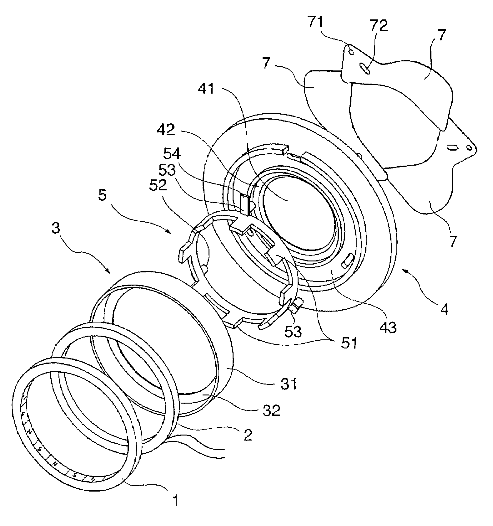
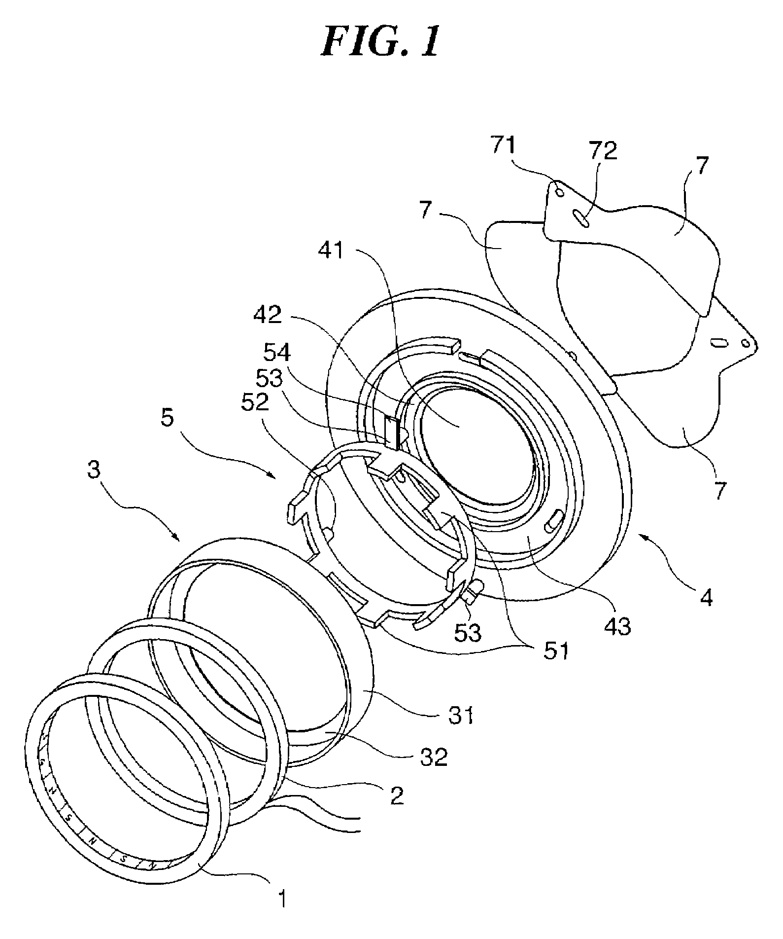
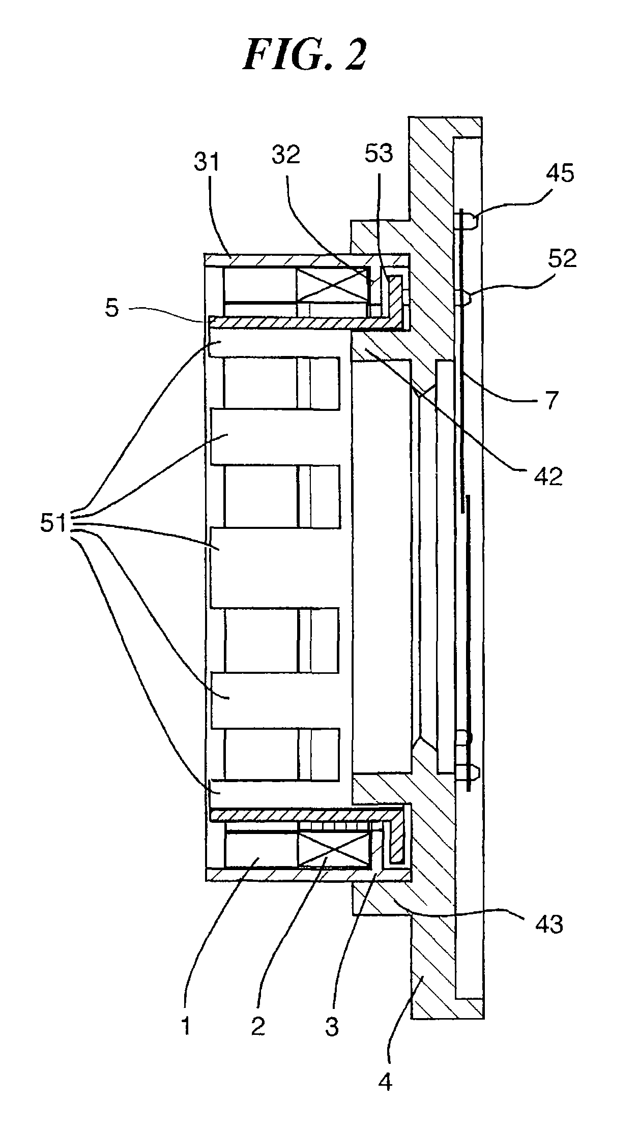
[0036]FIG. 1 is an exploded perspective view of a light amount controller according to the first embodiment. FIG. 2 is a cross-sectional view in the axial direction of the light amount controller in FIG. 1 in an assembled state thereof. FIG. 3A is a front view of the light amount controller with shutter blades thereof closed. FIG. 3B is a front view of the light amount controller with the shutter blades thereof open.

[0037]As shown in FIGS. 1 to 3, the light amount controller is comprised of a light amount adjusting mechanism including a base plate 4 and the shutter blades 7, and a driving device including a magnet 1, a coil 2, a stator yoke 3, and a rotor yoke 5.

[0038]The magnet 1 is in the form of a hollow cylinder, and has an inner peripheral surface thereof, as magnetized sections, circumferentially divided into n sections (16 sections in the present embodiment) which are magnetized such that they have alternately ...

second embodiment

[0081]Next, a description will be given of the present invention.

[0082]FIG. 6 is an exploded perspective view of a driving device according to the second embodiment. FIG. 7 is a cross-sectional view in the axial direction of the driving device in FIG. 6 in an assembled state thereof.

[0083]As shown in FIGS. 6 and 7, the driving device is comprised of a magnet 11, a coil 12, a stator yoke 13, a rotor yoke 15, and a rotor pin 16.

[0084]The magnet 11 is in the form of a hollow cylinder, and has an outer peripheral surface thereof circumferentially divided into n sections (four sections in the present embodiment) magnetized such that they have alternately different S and N poles (outer-periphery magnetization). The magnet 11 is disposed on an inner periphery side of the rotor yoke 15 when the driving device is assembled.

[0085]The coil 12 is formed by numerous lead wires wound into a general hollow cylindrical form, and is disposed coaxially with the magnet 11 in axially side-by-side relat...


PUM


Abstract

A driving device which makes it possible to reduce the moment of inertia of a rotor and increase torque. A magnet is formed to have a hollow cylindrical shape and has magnetized sections which are magnetized to have alternately different poles in a circumferential direction thereof. A coil is wound coaxially with the magnet and is disposed in axially side-by-side relation to the magnet. A stator yoke is formed of a soft magnetic material and fixes the magnet and the coil. A rotor yoke is formed of a soft magnetic material, and has magnetic pole portions formed in opposed relation to the magnetized sections, for being magnetized by the coil. The rotor yoke is supported in a manner rotatable with respect to the stator yoke. An rotation restricting part limits a range of rotation of the rotor yoke within a predetermined angle.

Description

BACKGROUND OF THE INVENTION[0001]1. Field of the Invention[0002]The present invention relates to a driving device configured to rotate a rotor yoke, and a light amount controller incorporating the driving device as a drive source thereof.[0003]2. Description of the Related Art[0004]Conventionally, there have been proposed various types of small-sized and slim driving devices (see e.g. Japanese Laid-Open Patent Publications (Kokai) No. 2002-272082 and No. 2002-049076). Now, FIGS. 8 and 9 show a conventional driving device disclosed in Japanese Laid-Open Patent Publications (Kokai) No. 2002-272082.[0005]FIG. 8 is an exploded perspective view of the conventional driving device. FIG. 9 is a cross-sectional view in the axial direction of the driving device in an assembled state thereof.[0006]As shown in FIGS. 8 and 9, the driving device is comprised of a magnet 101, a coil 102, a stator 104, a base plate 105, a magnet presser 106, shutter blades 107, and a cover 109.[0007]The magnet 101 ...

Claims


Application Information

Patent Timeline
Patent Type & Authority Patents(United States)
IPC IPC(8): H02K37/12G03B9/08H02K41/00
CPCG03B9/14G03B9/22H01F7/14H02K26/00H02K37/14
Inventor YASUDA, HIROMU
Owner CANON KK
Why Eureka
Try Eureka