Analog electronic timepiece

An electronic clock, analog technology, applied to electromechanical clocks, visual indication of time, clocks and other directions, can solve the problems of inability to realize two functions of analog clocks, clock jumping, easy to exceed holding energy, etc.

Inactive Publication Date: 2001-08-08
CITIZEN WATCH CO LTD
View PDF1 Cites 7 Cited by
  • Summary
  • Abstract
  • Description
  • Claims
  • Application Information

AI Technical Summary

Problems solved by technology

When the pointer is used as the object, since the shape is roughly set, the external disturbance energy is greatly affected by the size of the inertia. Since the appearance design is given priority, the larger the needle shape, the more different the shape will be, resulting in imbalance. Increased, easily exceeds retention energy
As a result, the clock jump phenomenon occurs, and the two functions of the aforementioned analog clock cannot be realized.
[0013] Based on the above reasons, it is necessary to give priority to the design of the appearance and to increase the holding energy for setting, so the power consumption of the stepping motor will inevitably increase.

Method used


Image

  • Analog electronic timepiece
  • Analog electronic timepiece
  • Analog electronic timepiece

Examples


no. 1 example

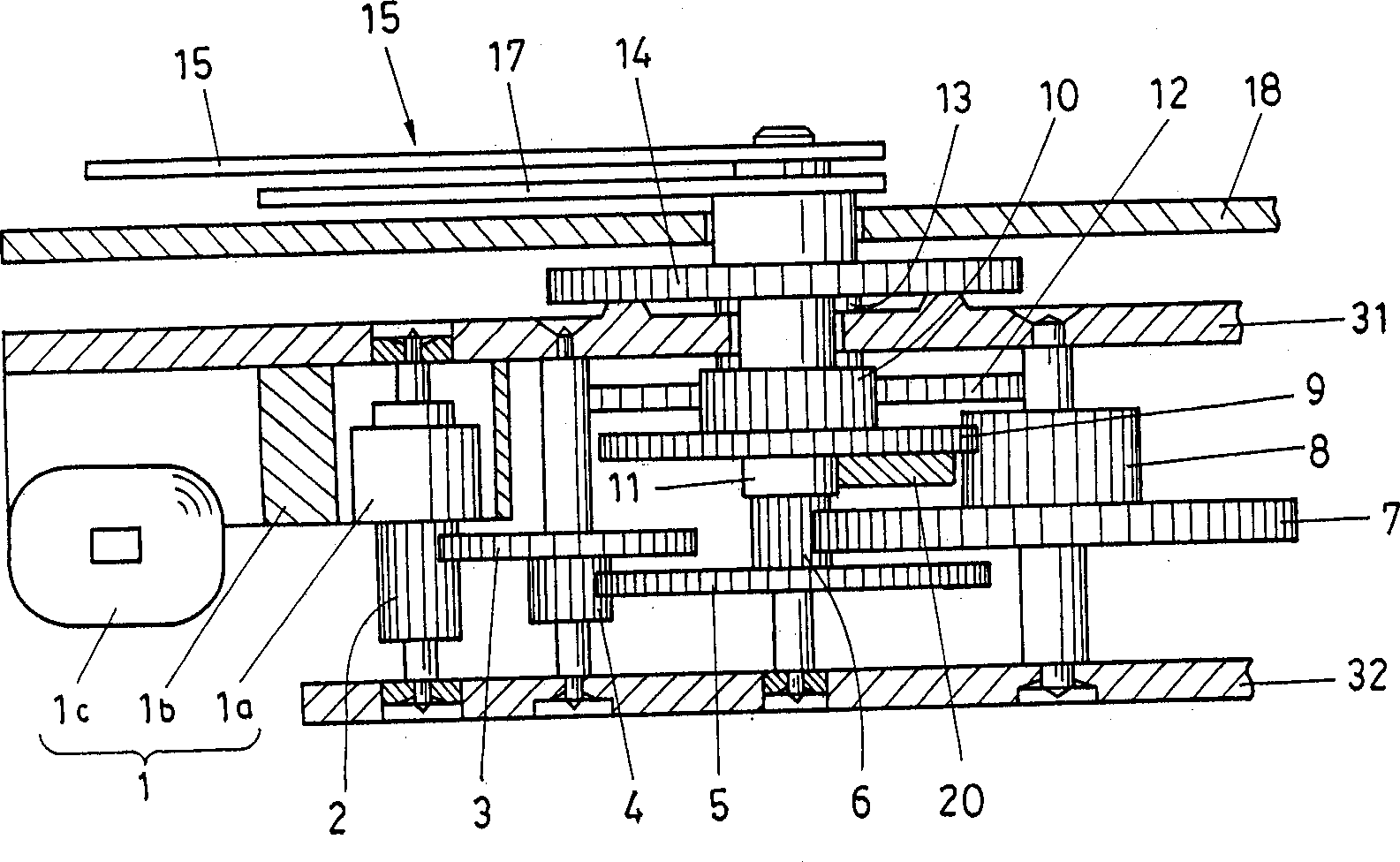
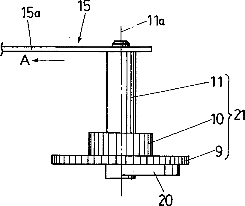
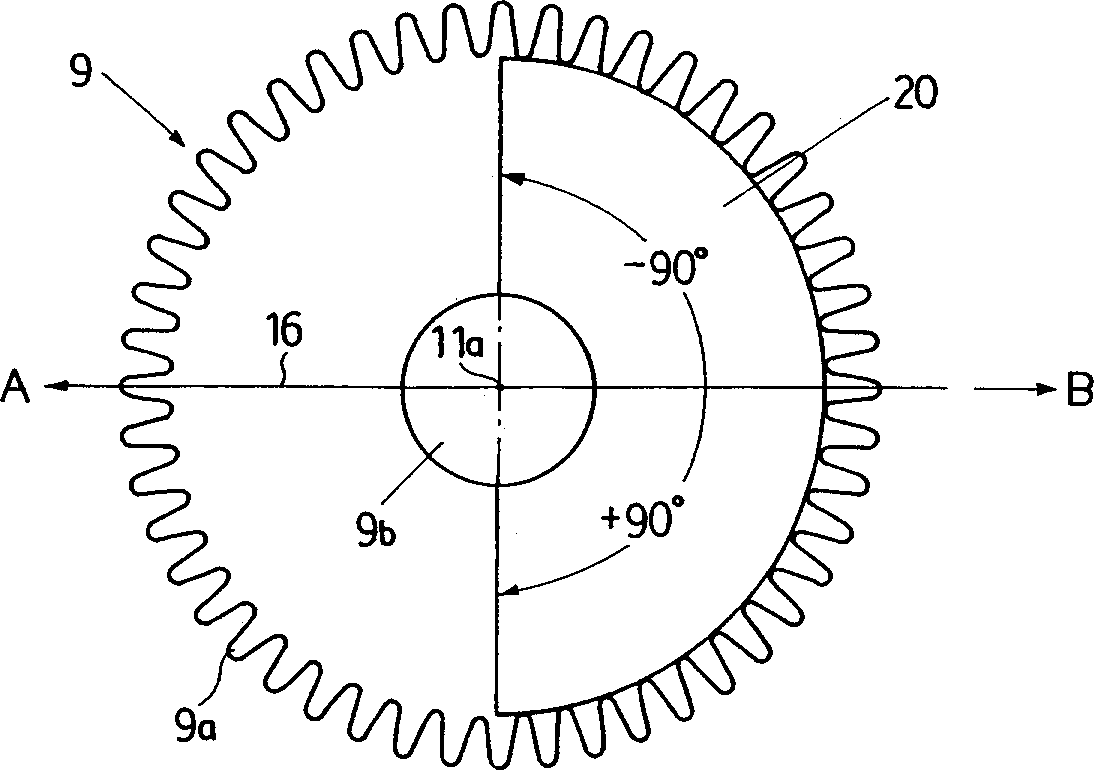
[0044] First, refer to Figure 1 to Figure 9 The first embodiment in which the present invention is applied to an analog double-hand electronic clock is described.

[0045] figure 1 It is a sectional view of the driving part of the analog two-hand electronic clock, the basic driving force transmission mechanism and Figure 19 The previous example shown has the same gear set construction, so it is the same as the Figure 19 Corresponding parts are denoted by the same symbol.

[0046] exist figure 1 Among them, 1 is a stepping motor, which is composed of a rotor 1a, a stator 1b, and a coil 1c. When it is driven, the rotor 1a rotates intermittently at 180° per second. The rotation of the rotor 1 a is transmitted to the fifth gear 3 coupled to the rotor pinion (pinion) 2 , and the fourth gear 5 is rotated by the fifth pinion 4 rotating integrally with the fifth gear 3 . The rotation of the fourth gear 5 is transmitted to the third gear 7 through the fourth pinion 6 which rota...

no. 2 example

[0087] Below, refer to Figure 10 ~ Figure 18 A second embodiment in which the present invention is applied to an analog three-hand electronic clock will be described.

[0088] Figure 10 is a cross-sectional view of the driving part of the analog three-hand electronic clock, and figure 1 The same parts are denoted by the same symbols.

[0089] exist Figure 10 Among them, when the rotor 1a of the stepping motor 1 rotates 180° per second intermittently, the rotation of the rotor 1a is transmitted to the fifth gear 3 combined with the rotor pinion 2, and the fifth small gear 3 integrally rotates with the fifth gear 3 Gear 4 rotates the fourth gear 5 .

[0090] The fourth gear 5 rotates integrally with the fourth pinion 6 and the fourth shaft 25 to rotate the second hand 19 attached to the tip of the fourth shaft.

[0091] Moreover, the rotation of the fourth shaft 25 is transmitted to the third gear 7 through the fourth pinion 6, and further transmitted to the second gear...


PUM


Abstract

An analog electronic timepiece capable of decelerating the rotation of a rotor (1a) of a step motor (1) through a train wheels before it is transmitted to an hour hand (17) and a minute hand (15), wherein the gravity center of a second shaft rotating body comprising a center wheel gear (9), a center wheel pinion (10), and a second shaft (11) to which the minute hand (15) is installed is displaced by an angle range of less than + / -90 DEG , from the axis of the second shaft (11), in the direction opposite to the direction in which a time indicating part (15a) of the minute hand (15) is extended so as to reduce a moment on the second shaft (11) caused by the minute hand (15) and the second shaft rotating body, whereby a breakage of the hand due to disturbance can be prevented even if the value of the holding energy of the step motor (1) is reduced.

Description

technical field [0001] The present invention relates to an analog electronic clock that displays time by hands, and particularly relates to a technique for reducing power consumption. Background technique [0002] The clock is not only used to know the correct time, but also has the function of so-called decoration. In almost all clocks, the design plays an important role. [0003] Most of the current clocks such as watches are generally electronic clocks using crystal oscillators, including digital clocks that use numbers to represent the time, and analog clocks that use dials and hands to represent the time. This analog electronic clock must satisfy the following two functions at the same time. [0004] One is the function of driving the pointer to rotate at a certain angle within a set time; the other is the function of maintaining the pointer without causing the pointer to jump under external impact. [0005] Figure 19 It is an expanded view showing the configuration...

Claims


Application Information

Patent Timeline
Patent Type & Authority Applications(China)
IPC IPC(8): G04B19/02G04C3/00
CPCG04C3/008G04B19/02
Inventor 铃木一男町田任康南谷孝典高桥重之岛内岳明
Owner CITIZEN WATCH CO LTD
Why Eureka
Try Eureka