Power steering system

a technology of power steering and steering shaft, which is applied in the direction of electric steering, slip coupling, vehicle components, etc., can solve the problems of degrading the follow-up capability between the rotation of input shaft 3 and the rotation of output shaft 2, and the inability to provide predetermined frictional force, so as to reduce the moment of inertia and accurately determine the pressing force

Inactive Publication Date: 2001-05-15
MITSUBA CORP
View PDF14 Cites 6 Cited by
  • Summary
  • Abstract
  • Description
  • Claims
  • Application Information

AI Technical Summary

Benefits of technology

In consideration of the above circumstances, the present invention provides a power steering system based on a first objective to reduce the moment of inertia of the torque limiter, and on a second objective to accurately determine pressing force by a forcing member.
In the torque limiter in the power steering system as structured above, (i) the cylindrical portion, having the splines on the inner-peripheral surface, to which a shaft having splines which can be engaged with above splines is inserted, and (ii) the flange portion which must have a suitable accuracy for functioning as a friction clutch, are separately formed. Therefore, efficient manufacturing is possible in consideration of accuracy requirements relating to formation of each portion. In addition, both portions may be made of different materials; thus, efficiency of forming the limiter plate can be improved and relevant accuracy and strength conditions can be respectively improved.

Problems solved by technology

However, in a torque limiter having such a large outer diameter, which is rotated together with output shaft 2 and input shaft 3, the moment of inertia of this torque limiter 4 also becomes large, and there occur problems in that the driving force necessary for rotationally driving output and input shafts 2 and 3 is increased, and follow-up capability between rotation of input shaft 3 and rotation of output shaft 2 is degraded.
According to the above possibilities, there occurs another problem in that predetermined frictional force is not provided between limiter cover 5, friction plate 9, and limiter plate 7.

Method used


Image

  • Power steering system
  • Power steering system
  • Power steering system

Examples


first embodiment

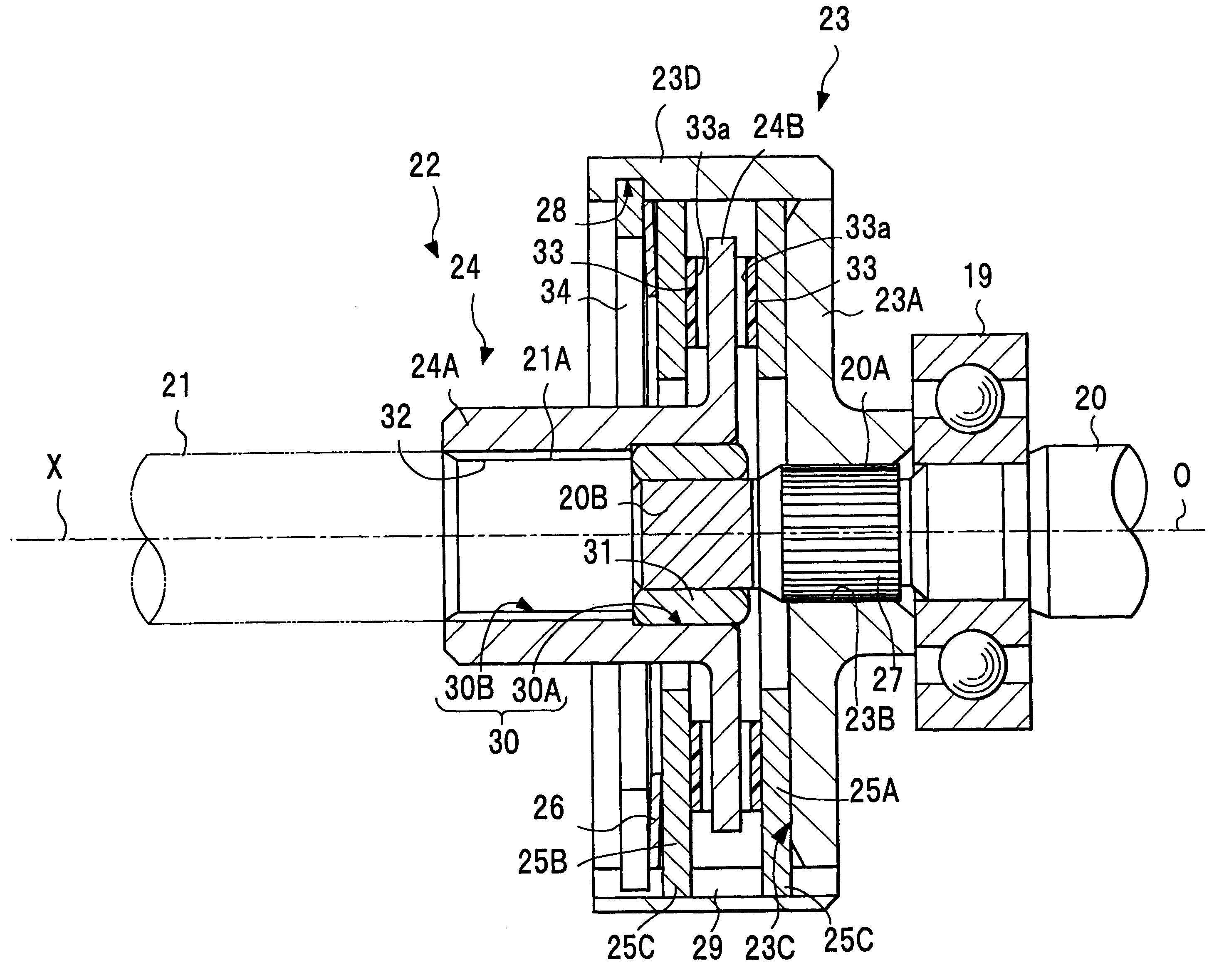
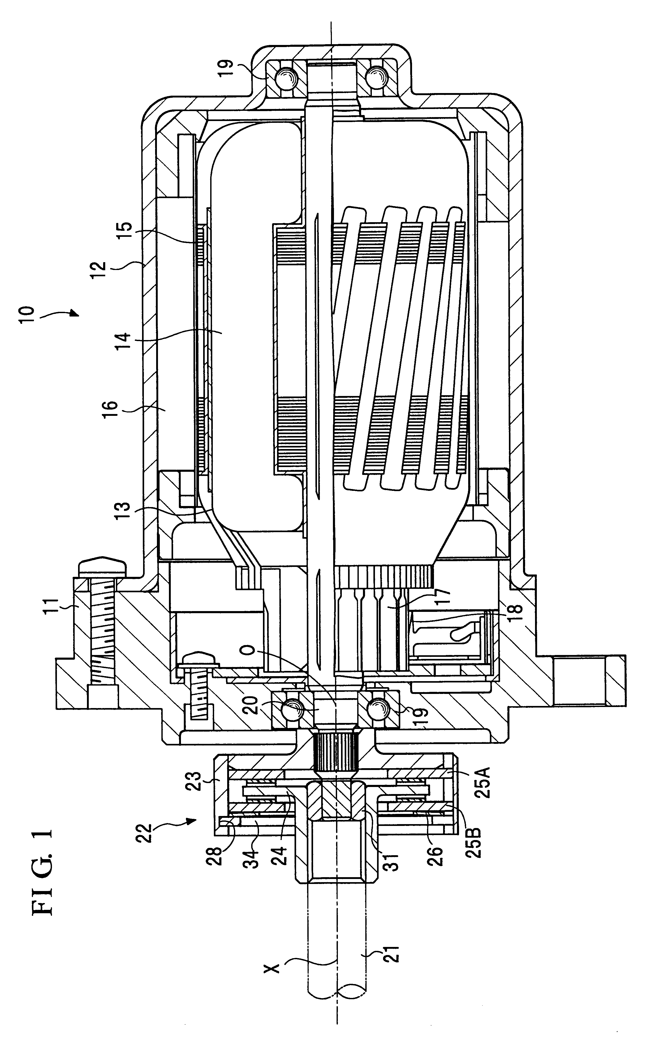
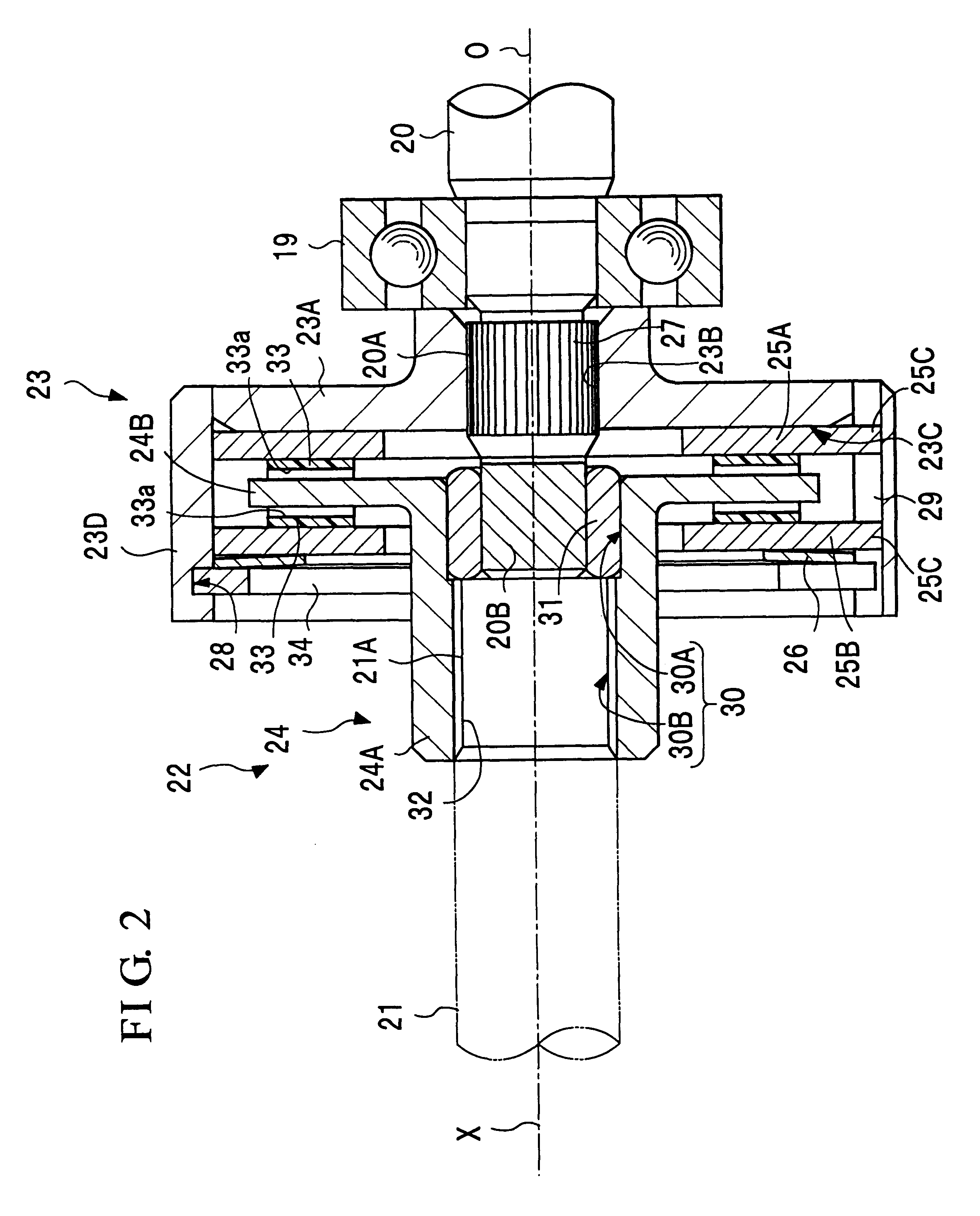
FIGS. 1-3 shows the present invention. In this embodiment, driving unit 10 corresponds to a conventional motor which includes bracket 11, yoke 12, armature 13, coil 14, core 15, magnet 16, commutator 17, brush 18, bearing 19, and output shaft 20. This output shaft 20 is coupled via torque limiter 22 to input shaft 21 of a steering unit of a vehicle or the like (not shown). The torque limiter 22 comprises limiter cover 23 as a rotating member of the present invention, attached such that this cover is rotatable together with output shaft 20, limiter plate 24 as a rotated member of the present invention, attached such that this plate is rotatable together with input shaft 21, and forcing member 26 for forcing this limiter plate 24 onto limiter cover 23 via a pair of cover disks (i.e., friction plates) 25A and 25B and realizing the integral rotation of limiter plate 24 and limiter cover 23 by frictional force generated by the forcing operation.

The output shaft 20 has a step-form structu...

second embodiment

According to the power steering system of the second embodiment as constructed above, flange portion 24B of limiter plate 24 forced by forcing member 26 is in contact with facing material 33 adhered on the upper surface 41A of the convex portion 41. Therefore, even though cover disk 25A is omitted at the bottom face 23C of limiter cover 23, it is only required that the upper surface 41A of the convex portion 41 is processed to have specific flatness. That is, in comparison with the entire bottom face 23C being similarly processed, time and labor can be reduced to improve efficiency, and limiter plate 24 and limiter cover 23 can be firmly in contact with each other and uniform frictional force can be generated.

It is also possible that, instead of providing convex portion 41 on the bottom face 23C of limiter cover 23, a facing material as mentioned above may be directly adhered on the bottom face 23C so as to make limiter plate 24 in contact with the upper surface of the facing materi...

third embodiment

FIGS. 5 and 6 show the arrangement of the In these figures, parts identical to those in FIGS. 1-4 are given identical reference numerals, and explanations thereof are omitted.

In torque limiter 72 of the present embodiment, limiter cover 23 itself is deformed so as to support forcing member 26, and only one cover disk 25 is provided between flange portion 24B and forcing member 26, as in the case of the above-explained second embodiment.

At the opening side of the cylindrical portion 23D of limiter cover 23, wall portion 23E is formed, in which the inner-peripheral area has two kinds of diameters and thus the larger diameter portion has a thinner wall thickness. In addition, step portion 23F is formed at the bottom face 23C side of the wall portion 23E. Furthermore, at some areas, closer to the bottom face 23C side than the step portion 23F, in the inner surface of cylindrical portion 23D, plural (three in the present embodiment) projecting portions as convex fitting portions 129 are...


PUM


Abstract

A power steering system to reduce the moment of inertia of the torque limiter and to accurately determine pressing force by a forcing member is provided. The torque limiter of the system has a basic structure in which a substantially-cylindrical rotating member which is rotatable together with one of the output shaft and the input shaft; and a rotated member which is rotatable together with the other of the output shaft and the input shaft, and which is forced toward the rotating member side by a forcing member supported by the rotating member. Typically, the rotating member is a substantially-cylindrical limiter cover with a bottom, and the rotated member is a limiter plate contained in the limiter cover. The forcing member may be supported by a concave portion formed in an inner-peripheral area of the limiter cover, or may be supported by a projecting portion which is formed by deforming the cylindrical portion of the limiter cover toward the inside. In the above basic structure, the rotated member may separately comprise a cylindrical portion, on the inner-peripheral surface of which plural splines are formed in parallel with its axial direction, these splines being engaged with the splines formed in the outer-peripheral surface of the other of the output shaft and the input shaft; and a flange portion, which is forced toward the rotating member side, by which the flange portion functions as a friction clutch. In this structure, efficiency of forming the limiter plate can be improved.

Description

BACKGROUND OF THE INVENTION1. Field of the InventionThe present invention relates to a power steering system for generating an auxiliary steering force for the steering of a vehicle such as a four-wheel-drive car or the like.2. Description of the Related ArtFIG. 16 shows an example of a power steering system. The power steering system as shown in FIG. 16 is disclosed in Japanese Patent Application, First Publication, No. Hei 9-84300, in which output shaft 2 of driving unit (i.e., motor) 1 for generating the above auxiliary steering force and input shaft 3 coupled to the steering unit of a vehicle are coupled via torque limiter 4. This torque limiter 4 comprises cylindrical limiter cover (or case) 5 having a bottom, fixed in a manner such that the cover is rotationally driven together with the output shaft 2, similar cylindrical cover 6 having a bottom, which covers from the opening side to the outer surface of the limiter cover 5, limiter plate (or boss) 7 which is arranged to be re...

Claims


Application Information

Patent Timeline
Patent Type & Authority Patents(United States)
IPC IPC(8): B62D5/04F16D7/00F16D7/02
CPCB62D5/043F16D7/025
Inventor ABE, HIDEAKIAOKI, SUSUMUFURUUCHI, HIDEKI
Owner MITSUBA CORP
Why Eureka
Try Eureka