
Electric straddled vehicle

A saddle-riding vehicle, electric technology, applied in electric scooters, motor vehicles, motorcycles, etc., can solve the problems of poor weight balance, difficulty in providing lightweight and cheap electric two-wheelers, etc., to improve weight balance, High versatility and burden reduction effect

Active Publication Date: 2012-05-09
HONDA MOTOR CO LTD
View PDF3 Cites 6 Cited by
  • Summary
  • Abstract
  • Description
  • Claims
  • Application Information

AI Technical Summary

Problems solved by technology

[0010] However, in the electric vehicle described in Patent Document 1, since the rear wheels are driven by a motor coaxially provided with the rear axle, and the drive torque is obtained without a reduction mechanism, a dedicated motor with a large diameter is required, so it is difficult to provide Lightweight and inexpensive electric motorcycle, and since the electric motor and the control unit (motor driver) are housed in one arm provided on the left side of the swing arm in the vehicle width direction, the weight distribution on the left side of the vehicle body is relatively Larger than the right side of the hull resulting in poor weight balance
Then there is the possibility that the rigidity of the rocker arm must also be increased

Method used


Image

  • Electric straddled vehicle
  • Electric straddled vehicle
  • Electric straddled vehicle

Examples


Embodiment Construction

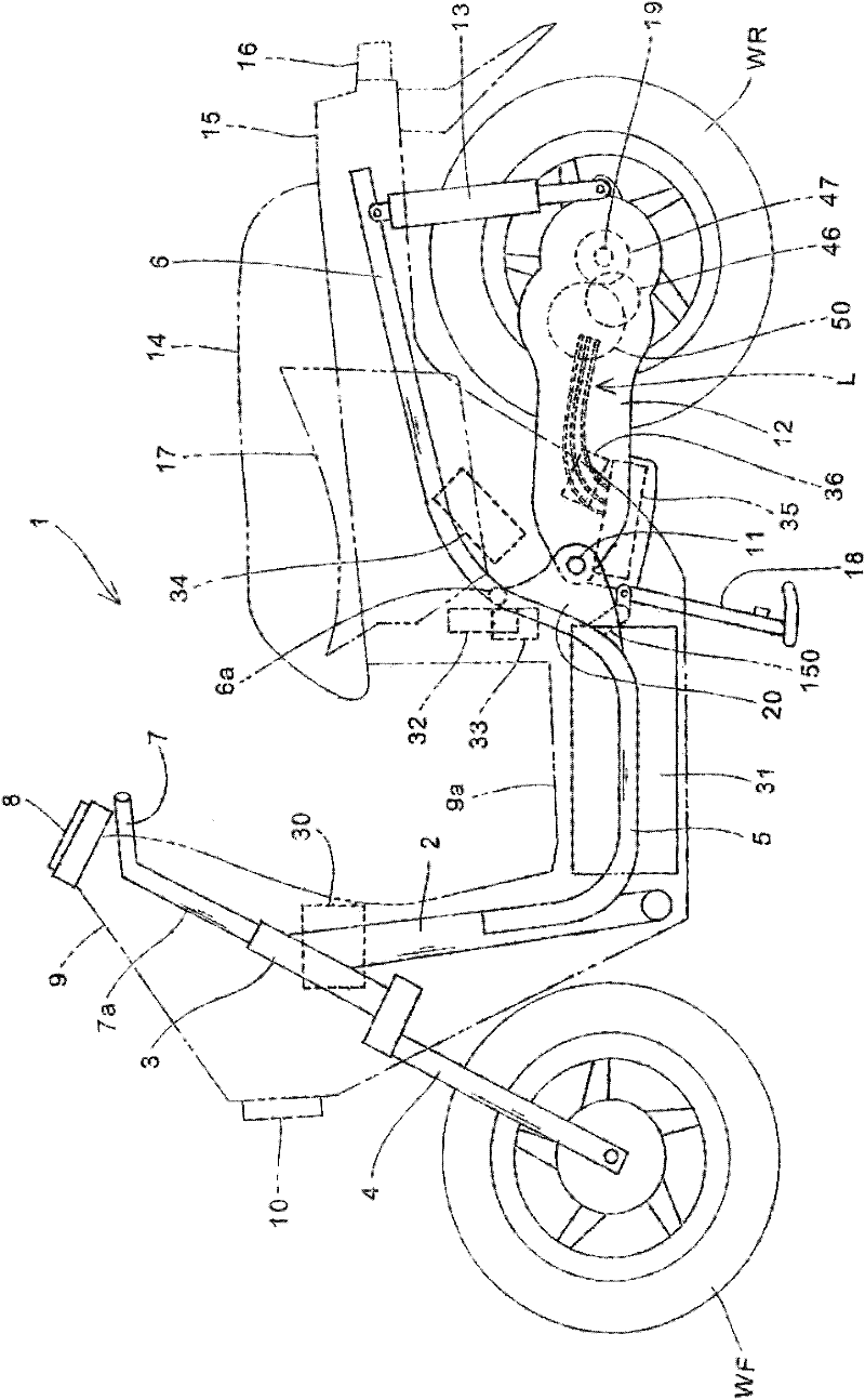
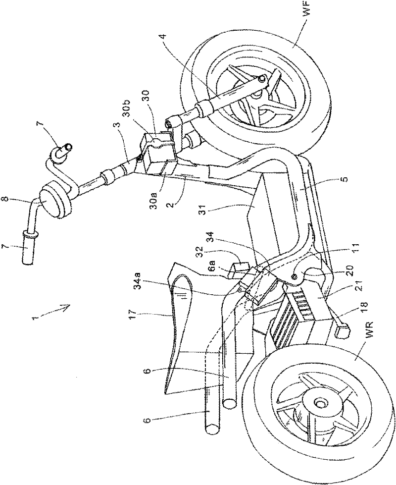
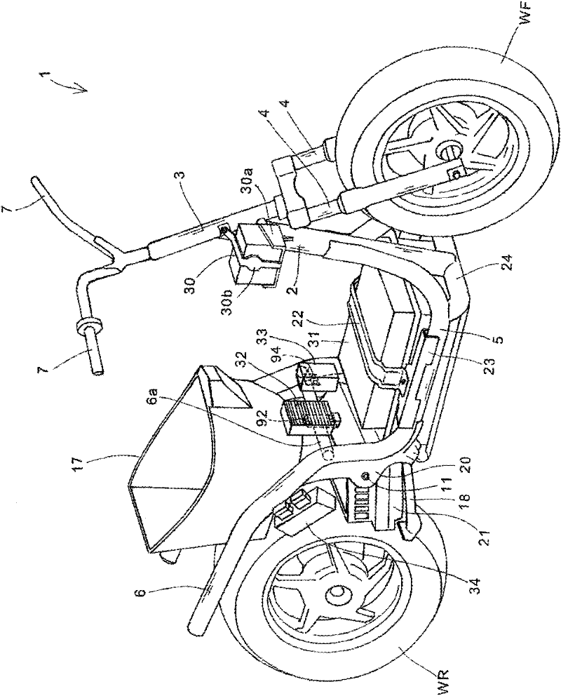
[0073] Hereinafter, preferred embodiments of the present invention will be described in detail with reference to the drawings. figure 1 It is a side view of a saddle-riding electric vehicle 1 according to an embodiment of the present invention. in addition, figure 2 It is a rear perspective view of the electric vehicle 1 with exterior parts removed. The electric vehicle 1 is a small two-wheeled motor vehicle with a low pedal 9a, and it is configured to use an electric motor 50 built in a rocker arm 12 (refer to Figure 4 ) drives the rear wheel WR. In addition, the high-voltage battery 31 that supplies electric power to the electric motor 50 can be charged by connecting an external power source to a charging port (not shown) provided in the vehicle body.

[0074] A head pipe 3 that rotatably pivotally supports a steering rod 7 a is coupled to a front side end portion of the main frame 2 . A steering handle 7 is attached to the upper portion of the steering rod 7a, and a p...


PUM


Abstract

An electric straddled vehicle which has, despite the fact that the vehicle is a lightweight and inexpensive vehicle using a small-sized, highly versatile motor, the balance of weight in the left-right in the width direction of the vehicle relative to the vehicle body centerline is optimized. An electric motor (250) is disposed within a cantilever swing arm (214) at a position at which, when viewed from a side of the vehicle body, the electric motor is superposed on the region in which a rear wheel (WR) is projected. A motor driver (216) is disposed within the swing arm (214) so as to straddlethe vehicle body centerline (C) at a position in front of the rear wheel (WR) relative to the vehicle body. The motor driver (216) is disposed in such a manner that the position (G2) of the center ofgravity thereof is offset to the side opposite to the side to which the electric motor (250) is offset from the vehicle body centerline (C). The motor driver (216) is provided behind a rocking shaft (215) relative to the vehicle body at a position close to the rocking shaft (215) and is inserted and mounted to a recess (308) open to the upper surface side of the swing arm (214). An FET (316) for conducting and interrupting an electric current to the motor is at least supported on the lower surface of a lid member (264) of the motor driver (216).

Description

technical field [0001] The present invention relates to an electric saddle-riding vehicle, in particular to an electric saddle-riding vehicle that drives driving wheels by an electric motor. Background technique [0002] Conventionally, an electric saddle-riding vehicle is known in which driving wheels are driven by an electric motor. [0003] Patent Document 1 discloses an arrangement in which, in a small electric vehicle having a cantilevered rocker arm that pivotally supports the rear wheel with one arm, the electric motor is divided into two parts by using a speed reducer composed of a planetary gear. The output shaft is arranged at the same position as the axle of the rear wheel, and the control device of the electric motor is housed inside the arm. [0004] In addition, in the electric vehicle described above, the arrangement of the electric motor and the storage battery as a power supply source becomes a major factor in terms of vehicle body layout. [0005] Patent ...

Claims


Application Information

Patent Timeline
IPC IPC(8): B62M7/12B62J9/00B62K25/20
CPCB62K11/10B62M7/12B62K2202/00B62K2204/00
Inventor 本田幸一郎中川英亮味村政秀岩上宽佐藤和夫新妻桂一郎
Owner HONDA MOTOR CO LTD
Learn More