Plasma display apparatus with electrode structure

a technology of plasma display and electrode structure, which is applied in the direction of address electrodes, static indicating devices, instruments, etc., can solve the problems of increasing achieve the effects of reducing the manufacturing cost of the plasma display panel, improving the flickering of the display image, and generating bright defects

Inactive Publication Date: 2010-03-16
LG ELECTRONICS INC
View PDF15 Cites 1 Cited by
  • Summary
  • Abstract
  • Description
  • Claims
  • Application Information

AI Technical Summary

Benefits of technology

[0012]The present invention is to provide a plasma display apparatus from which a transparent ITO electrode is eliminated, thereby reducing a manufacturing cost of a plasma display panel, and improving flickering of a display image and generation of a bright defect.

Problems solved by technology

The transparent electrodes 102a and 103a cause an increase of a manufacturing cost of the plasma display panel.

Method used


Image

  • Plasma display apparatus with electrode structure
  • Plasma display apparatus with electrode structure
  • Plasma display apparatus with electrode structure

Examples


Embodiment Construction

[0039]Preferred embodiments of the present invention will be described in a more detailed manner with reference to the drawings.

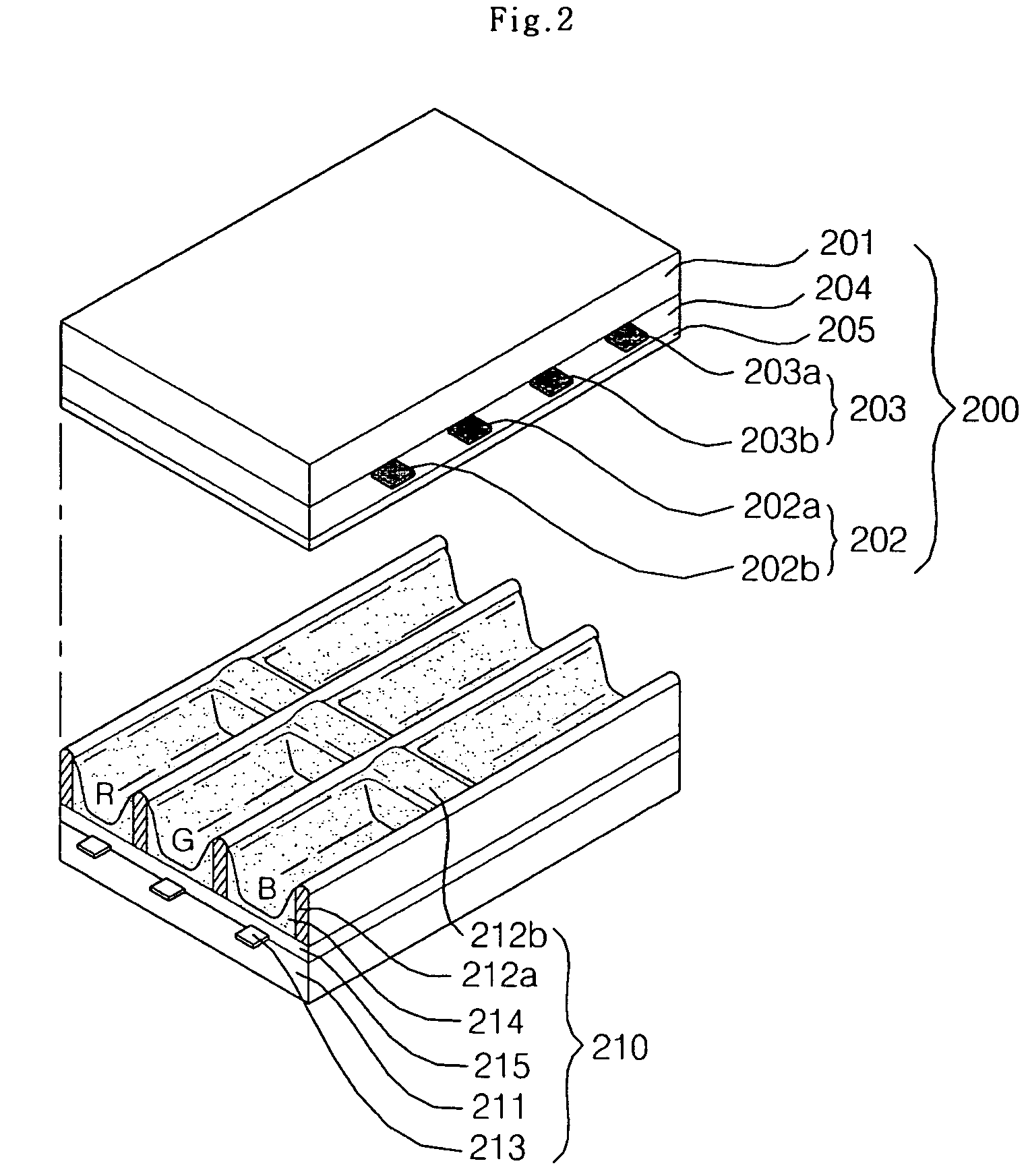
[0040]FIG. 2 is a perspective view illustrating a structure of a plasma display panel according to an exemplary embodiment of the present invention.

[0041]Referring to FIG. 2, the plasma display panel includes an upper panel 200 and a lower panel 210 sealed at a distance. The plasma display panel includes an address electrode 213 formed on a lower substrate 211 in the direction of intersecting with a sustain electrode pair 202 and 203; and a barrier rib 212a and 212b formed over the lower substrate 211 and partitioning a plurality of discharge cells.

[0042]The upper panel 200 includes the sustain electrode pair 202 and 203 formed on an upper substrate 201 by pair. The sustain electrode pair 202 and 203 is classified into a scan electrode 202 and a sustain electrode 203 depending on its function. The sustain electrode pair 202 and 203 is covered with an upper ...


PUM


Abstract

Provided is a plasma display apparatus. The plasma display apparatus includes an upper substrate, a plurality of first electrodes and second electrodes formed over the upper substrate, a lower substrate disposed facing the upper substrate, and a plurality of third electrodes formed over the lower substrate. At least one of the plurality of first electrodes and second electrodes is formed as one layer, and the first electrodes or the second electrodes are sequentially formed in at least one portion.

Description

[0001]This Nonprovisional application claims priority under 35 U.S.C. § 119(a) on Patent Application No. 10-2006-0055475 filed in Korea on Jun. 20, 2006, the entire contents of which are hereby incorporated by reference.BACKGROUND OF THE INVENTION[0002]1. Field of the Invention[0003]The present invention relates to a plasma display apparatus, and more particularly, to a panel provided to a plasma display apparatus.[0004]2. Description of the Background Art[0005]In a plasma display panel, a barrier rib formed between an upper substrate and a lower substrate forms one unitary cell. Main discharge gas such as neon (Ne), helium (He) or a mixture (He+Ne) of neon and helium and inert gas containing a small amount of xenon (Xe) are filled in each cell. When a discharge is induced using a high frequency voltage, the inert gas generates vacuum ultraviolet rays and excites phosphors provided between the barrier ribs, thereby embodying an image. The plasma display panel is attracting attention...

Claims


Application Information

Patent Timeline
Patent Type & Authority Patents(United States)
IPC IPC(8): H01J17/49G09G3/20G09G3/288G09G3/291G09G3/296G09G3/298H01J11/22H01J11/24H01J11/34
CPCH01J11/12H01J11/24H01J11/32H01J11/26H01J2211/245H01J2211/323
Inventor BAE, JONG WOON
Owner LG ELECTRONICS INC
Why Eureka
Try Eureka