Fire detection method and apparatus

a fire detection and apparatus technology, applied in the electrical field, can solve the problems of limited use of devices based on this methodology, sensitivity optimization, and smoke from fires to sensors

Active Publication Date: 2010-03-16
AXONX FIKE CORP
View PDF16 Cites 4 Cited by
  • Summary
  • Abstract
  • Description
  • Claims
  • Application Information

AI Technical Summary

Problems solved by technology

However, a disadvantage of this approach is that it assumes that smoke from a fire will find its way to a sensor at an instant in the fire's progression when there is still time for action to be taken to put out the fire before excessive damage occurs.
However, a possible disadvantage of this approach is that its sensitivity is optimized for only particular types of fuels.
Thus, use of devices based on this methodology is usually limited to environments where probable fires could be caused by only a limited number of materials (i.e., natural gas, oil, methanol).
Another disadvantage of this approach is that the sensors that are used with such methodologies are highly sensitive to the distance between the source of radiation (flames) and the actual sensor element.
Thus, the areas that can be monitored by these devices can be quite limited in size (i.e., since making their sensitivity high so as to cover a greater area can result in false alarms).
It is common practice to place these devices only in close proximity to installations that pose high fire risks.
Additionally, the relatively high cost of such sensors prevents the use of a great number of them to monitor large production and commercial spaces.
However, this approach does not utilize the reliability enhancing technique of analyzing such data in spectral or wavelength ranges that are characteristic of particular combustion processes.
This method provides a means of early fire detection within the framework of standard CCTV surveillance systems, and it is insensitive, within a monitoring camera's allowable range, to the distance between the camera and a light source which may be due to the presence of a fire.
However, a significant disadvantage of this method is that it can be only employed when flames are directly visible by the imaging device.
Inexpensive technologies that can provide such fire detection improvements can significantly affect public safety in general.

Method used


Image

  • Fire detection method and apparatus
  • Fire detection method and apparatus
  • Fire detection method and apparatus

Examples


Embodiment Construction

[0032]Before explaining at least one embodiment of the present invention in detail, it is to be understood that the invention is not limited in its application to the details of construction and to the arrangements of the components set forth in the following description or illustrated in the drawings. The invention is capable of other embodiments and of being practiced and carried out in various ways. Also, it is to be understood that the phraseology and terminology employed herein are for the purpose of description and should not be regarded as limiting.

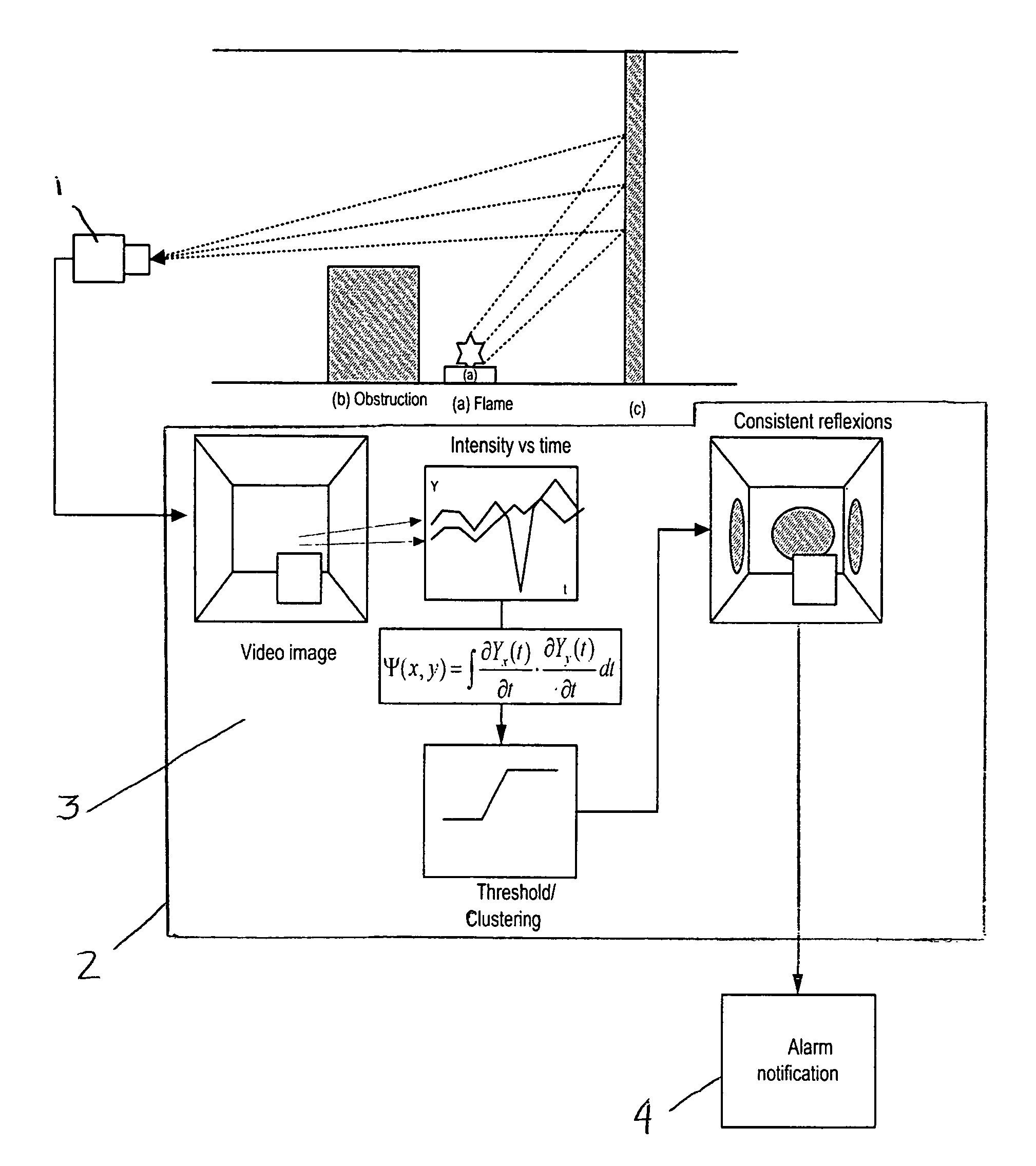
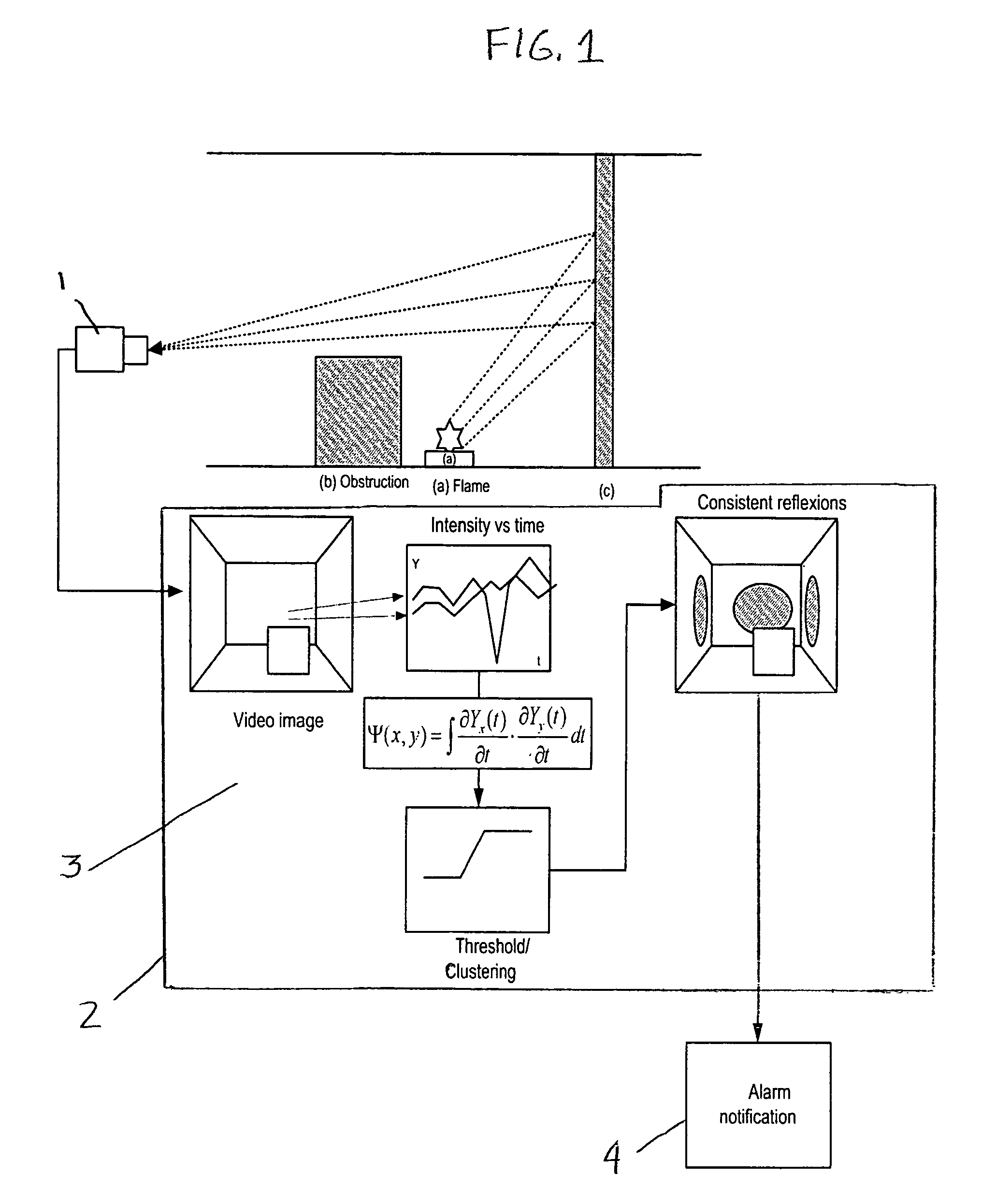
[0033]FIG. 1 shows a preferred embodiment of the fire detection method and apparatus of the present invention that can operate within the framework of the ordinary Closed Circuit Television (CCTV) surveillance system for commercial, outdoor, industrial and residential installations.

[0034]In a preferred embodiment, the present invention monitors the images being collected from a monitored area so as to form of a series of matrices (...


PUM


Abstract

The present invention provides a method and apparatus for detecting fire in a monitored area even if the flames are hidden behind obstructing objects. The steps of this method include: (a) detecting and capturing, at a prescribed frequency, video images of the monitored area, (b) converting the captured images into two-dimensional bitmaps of the temporally varying brightness values observed in the captured images, wherein the spatial resolution of this bitmap is determined by the number of pixels comprising the bitmaps, (c) specifying for any two of the pixels in the bitmaps a temporal coherence factor whose magnitude is a measure over a prescribed time of the similarities observed in the temporal variations of the brightness values being captured at each of the bitmap's pixels, (d) computing this temporal coherence factors for each of the prescribed set of pixels in the captured images, and (e) analyzing the computed temporal coherence factors to identify those sets of pixels that have temporal coherence factors whose values are above a prescribed threshold value, wherein this prescribed threshold value is set so as to identify those pixels that correspond to regions of the monitored area whose temporal variations in brightness indicate that the source of this brightness is a fire in the monitored area.

Description

CROSS-REFERENCE TO RELATED APPLICATION[0001]This application claims the benefit of U.S. Provisional Patent Application No. 60 / 572,056, filed May 18, 2004 by the same inventor.BACKGROUND OF THE INVENTION[0002]1. Field of the Invention[0003]The present invention generally relates to electrical, condition responsive systems and methods. More particularly, this invention relates to a method and apparatus for detecting fire in a monitored area by detecting the light emission patterns of flames in the monitored area as a result of the detailed, computational analysis of a sequence of digitized images of the monitored area.[0004]2. Description of the Related Art[0005]Fire detectors are very important safety devices that can provide early warning of fire in a monitored area. Considerable efforts have been devoted to improving upon the technology used in fire detectors as a means of increasing their usefulness and reliability.[0006]One of the most commonly used methodologies for fire detecti...

Claims


Application Information

Patent Timeline
Patent Type & Authority Patents(United States)
IPC IPC(8): G06K9/00G06K9/62G08B17/12
CPCG06K9/00711G06V20/40
Inventor PRIVALOV, GEORGE
Owner AXONX FIKE CORP
Why Eureka
Try Eureka