Isolating well bore portions for fracturing and the like

a technology of fracturing and well bore portions, applied in the direction of wellbore/well accessories, fluid removal, sealing/packing, etc., can solve the problems of port bursting, limited fractures made at these ports, and increased cost of prior fracture isolation,

Active Publication Date: 2010-03-23
CUGNET MATTHEW
View PDF8 Cites 31 Cited by
  • Summary
  • Abstract
  • Description
  • Claims
  • Application Information

AI Technical Summary

Benefits of technology

[0020]The apparatus and method of the present invention allow placement of the isolated portion of the well bore virtually anywhere along the well bore while preventing communication between the current isolated portion and prior isolated portions of the well bore. The upper and lower packers are set in the open horizontal well bore with an open communication path from the tubing string to the desired formation location through the open sliding sleeve. The sliding sleeve is simple, with the only moving parts being a sliding relative movement between the upper and lower sleeves.

Problems solved by technology

The present systems for isolating prior fractures typically increase cost, pumping time, and complexity, and as well only a limited number of fractures can be placed.
For example this initial rupture pressure might be 1000 pounds per square inch (psi), and the fracture made at these ports is limited to the fracture that can be made with a pressure of 1000 psi, since increasing the pressure above this may cause the next adjacent ports to rupture.
The liner with the ball seats is left in the well which complicates future well repair and re-working.
This system was initially popular but has been found to allow communication between fractures since the gel plugs do not seal well enough to resist the high pressures, often 3000 psi or more, of a fracturing operation.
This system's main drawback is the time required for the cement to harden sufficiently.
With a conventional fracturing operation costing thousands of dollars an hour, this is not economically feasible on any but the most productive wells.

Method used


Image

  • Isolating well bore portions for fracturing and the like
  • Isolating well bore portions for fracturing and the like
  • Isolating well bore portions for fracturing and the like

Examples


Embodiment Construction

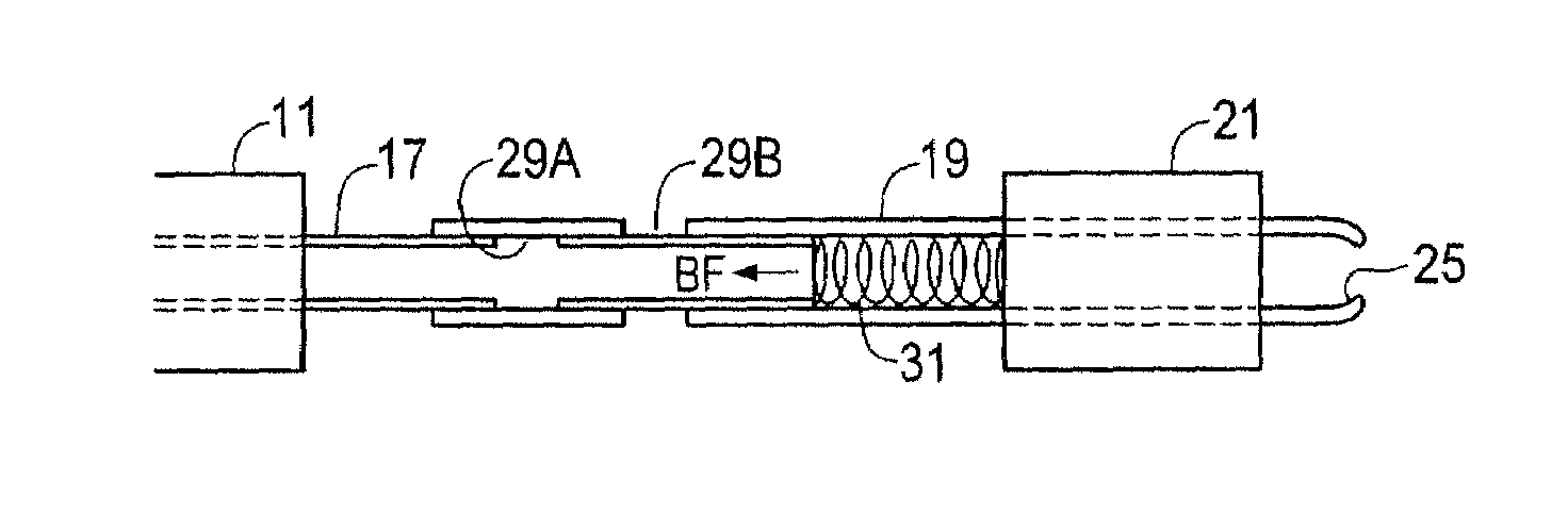
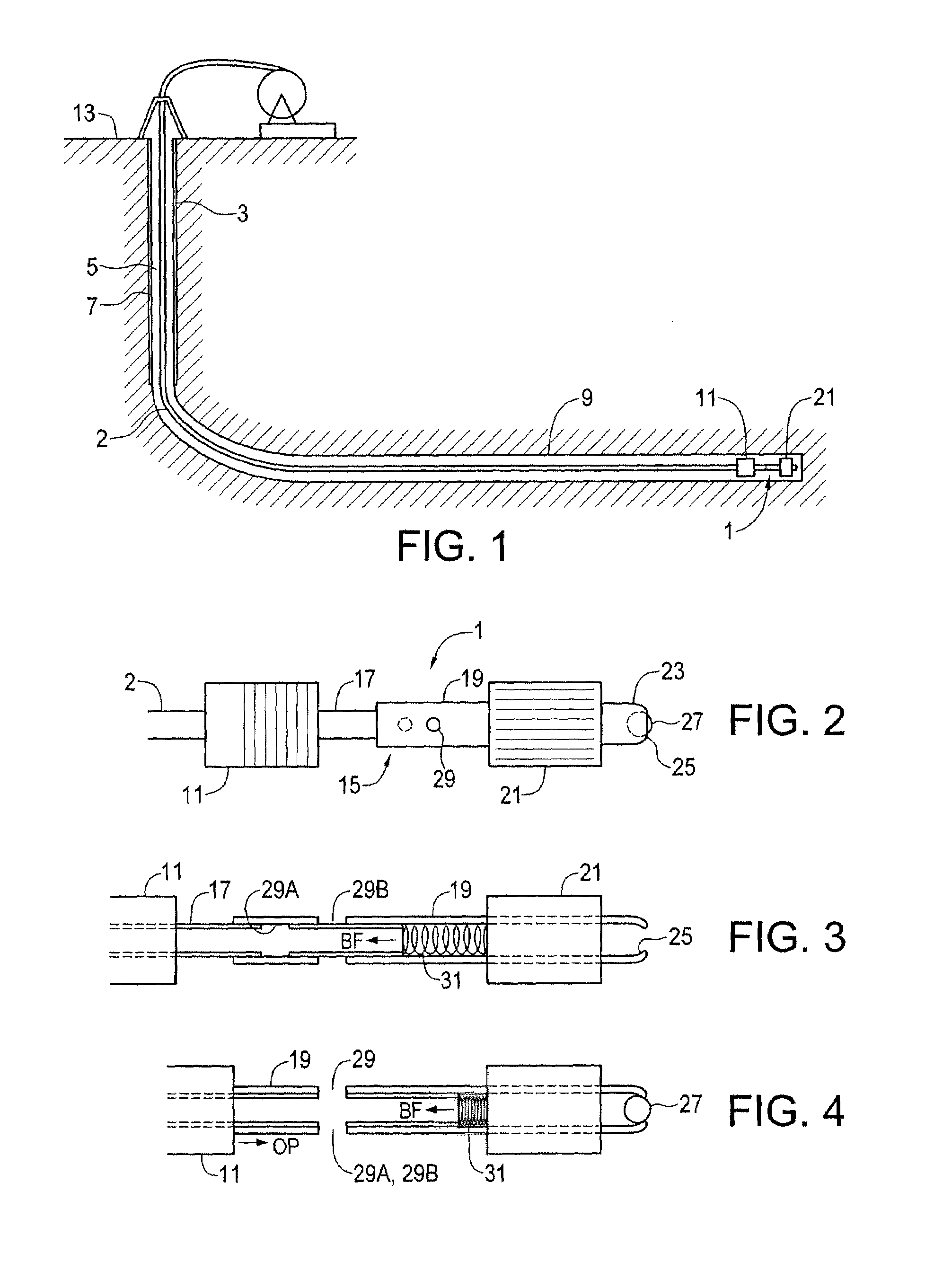
[0030]FIGS. 1 and 2 schematically illustrate a side view of an embodiment of an apparatus 1 of the present invention for isolating a portion of an open horizontal well bore and for providing pressurized fluid to the isolated well portion. The apparatus 1 is illustrated in FIG. 1 attached to the bottom end of a coiled tubing string 2 in a typical horizontal well 3 such as is commonly drilled for recovering hydrocarbons such as oil and gas from underground formations. The well 3 comprises a generally vertical section of well bore 5 that is typically lined with a casing 7. The well 3 curves from vertical to horizontal when the desired formation is reached, and a section of horizontal well bore 9 extends through the formation. The horizontal well bore 9 is not cased, but rather is what is commonly referred to as an open hole or open well bore. Thus the bare formation is exposed along the length of the horizontal well bore 9.

[0031]Typically once the well 3 has been drilled and the vertic...


PUM


Abstract

An apparatus and method for isolating a portion of a well bore and providing pressurized fluid thereto includes an upper packer, a lower packer, and a sliding sleeve between them. A seat is defined at the open bottom end of the lower sleeve and a sealing element is configured to seal the seat. A bias force urges the sliding sleeve toward a closed position. The apparatus moves along the bore and the lower packer is set at a desired location, and then an opening force is exerted on the tubing to move the sliding sleeve to the open position. After the lower packer is set and the sliding sleeve is open, the upper packer is set to isolate a portion of the well bore between the packers with the sliding sleeve in the open position to provide a flow path from the tubing string to the formation between the packers.

Description

PRIORITY[0001]This application claims priority to and benefit of Canadian Application[0002]Serial No. 2,654,447, filed on Feb. 17, 2009, which is herein incorporated by reference in its entirety.FIELD[0003]This invention is in the field of horizontal wells for hydrocarbons and in particular fracturing such wells to increase production in the wells.BACKGROUND[0004]Conventionally, wells for oil and gas recovery are substantially vertical. A well bore is drilled from the surface to a position below a desired hydrocarbon containing formation, and then a casing, basically a steel pipe with a diameter just slightly smaller than the well bore, is placed inside the walls of the well bore and cemented into place. The walls of the casing that are located within the desired formation are perforated, and then the formation is fractured by pumping sand or a like proppant into the cased hole at high pressure. The pressurized proppant enters the formation through the perforations in the casing and...

Claims


Application Information

Patent Timeline
Patent Type & Authority Patents(United States)
IPC IPC(8): E21B33/12
CPCE21B33/124E21B34/14E21B43/26E21B43/27E21B34/142
Inventor CUGNET, MATTHEW
Owner CUGNET MATTHEW
Why Eureka
Try Eureka