Dynamic voltage scaling method of CPU using workload estimator and computer readable medium storing the method

a dynamic voltage scaling and workload estimation technology, applied in the direction of liquid/fluent solid measurement, instruments, nuclear elements, etc., can solve the problems of affecting the stability of the system, the workload of the basic block is changed, and the real time system can be severely damaged

Active Publication Date: 2010-03-23
SAMSUNG ELECTRONICS CO LTD
View PDF9 Cites 16 Cited by
  • Summary
  • Abstract
  • Description
  • Claims
  • Application Information

AI Technical Summary

Problems solved by technology

Accordingly, the lowering of an operating voltage too much to reduce the power consumption of a CPU may cause a delay of a response to the particular request over the deadline so that the real time system can be severely damaged.
When the workload variation of the code segment is mostly distributed at a level quite lower than the maximum workload value, since the operating voltage is set to be higher than an actually needed operating voltage, the worst case execution time algorithm has a problem that the consumption of power by the CPU increases.
In an actual case, however, due to a hardware characteristic such as a cache or memory delay, the workload of the basic block is changed, and is not maintained constant.
As a result, the basic block code segment algorithm also has the problem of unnecessary power consumption because the operating voltage is set based on the maximum workload value as in the worst case execution time algorithm.
Thus, since the workload between the basic blocks is too small to apply an operating voltage changed by the DVS between the basic blocks, the changed operating voltage cannot be applied between the basic blocks.
Thus, hundreds of thousands of scaling points are generated with respect to an application program having a practical size, which are difficult to extract.

Method used


Image

  • Dynamic voltage scaling method of CPU using workload estimator and computer readable medium storing the method
  • Dynamic voltage scaling method of CPU using workload estimator and computer readable medium storing the method
  • Dynamic voltage scaling method of CPU using workload estimator and computer readable medium storing the method

Examples


Embodiment Construction

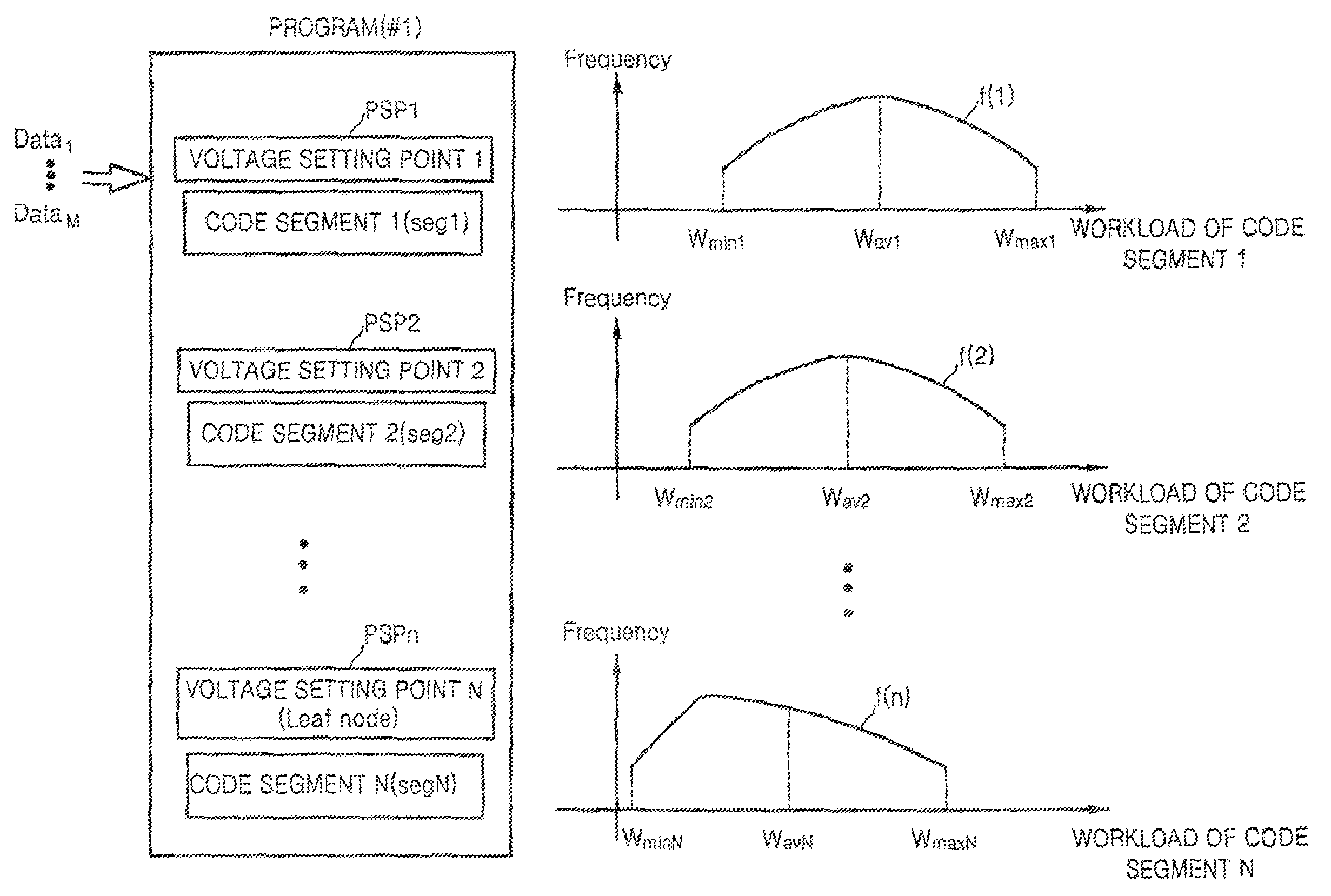
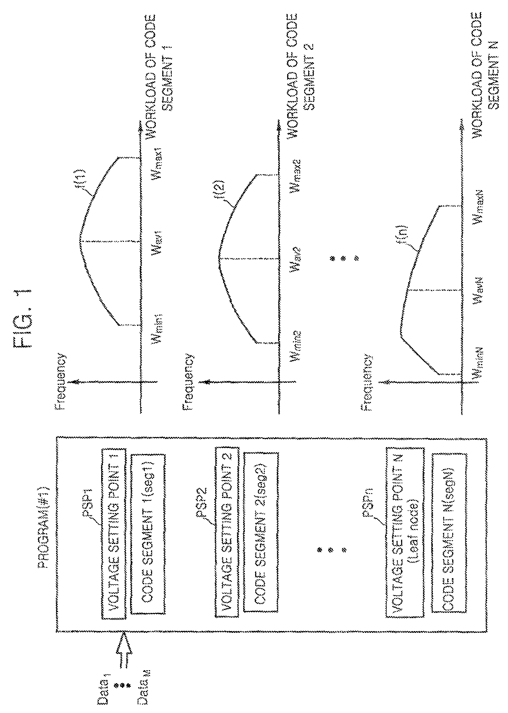
[0022]FIG. 1 is a conceptual view of voltage setting point setting and workload profiling according to an exemplary embodiment of the present invention. Referring to FIG. 1, a predetermined program #1) is divided into a plurality of code segments seg1 through segN. Voltage setting points PSP1 through PSPn are set to correspond to the respective code segments seg1 through segN. The program is executed based on data value Data1 and a workload value for each of the code segments seg1 through segN is measured.

[0023]Histograms f(1) through f(n) showing the distribution of workload values to the respective code segments seg1 through segN are obtained by executing the program while changing the data value from Data2 to DataM and measuring the workload value to each of the code segments seg1 through segN corresponding to each of the changed data values from Data2 to DataM. Average workload values Wav1 through WavN, the minimum workload values Wmin1 through WminN, and the maximum workload va...


PUM


Abstract

A method for scaling a dynamic voltage of a CPU is achieved by setting a voltage setting point for each of a plurality of code segments of a program, and profiling workload by measuring a workload variation of each of the code segments based on data that changes whenever measured, selecting a plurality of combinations, each having a plurality of voltage setting points, and calculating workload estimators corresponding to the voltage setting points of each of the selected combinations based on the workload variation measured in the workload profiling operation, selecting an optimal combination that consumes a least energy of the CPU based on the workload estimators, and determining whether a real time constraint is satisfied when an operating voltage is set based on the workload estimator corresponding to each of the voltage setting points of the optimal combination during runtime, and setting the operating voltage based on a result of the determination.

Description

CROSS-REFERENCE TO RELATED PATENT APPLICATION[0001]This application claims priority under 35 U.S.C. §119 from Korean Patent Application No. 10-2006-0010883, filed on Feb. 3, 2006, the disclosure of which is hereby incorporated by reference herein as if set forth in its entirety.BACKGROUND OF THE INVENTION[0002]1. Technical Field[0003]The present disclosure relates to a dynamic voltage scaling of a CPU, and more particularly, to a method of scaling the dynamic voltage of a CPU by which a workload is profiled in units of code segments having the same size and low power consumption and a real time constraint or deadline is guaranteed using a workload estimator calculated by the average workload, and a computer readable medium storing the method.[0004]2. Discussion of the Related Art[0005]A dynamic voltage scaling (DVS) function of a CPU is one of various hardware characteristics that is devised to reduce an electric power consumed by the CPU. To properly utilize the DVS function, a met...

Claims


Application Information

Patent Timeline
Patent Type & Authority Patents(United States)
IPC IPC(8): G06F1/26G01M19/00G06F1/00G06F11/30G06F9/44G06F9/45G01M99/00
CPCG06F1/3203G06F1/3243Y02B60/1239Y02D10/00E03F5/0401E03F5/0411
Inventor HONG, SUNG-PACKYOO, SUNG-JOO
Owner SAMSUNG ELECTRONICS CO LTD
Why Eureka
Try Eureka