Linear electron beam tube and circuit

A linear electron beam and electron tube technology, applied in the field of electron tubes, can solve the problems of difficult conversion and control of multiple lamp tubes, and achieve the effect of easy conversion and control, and simple operation

Inactive Publication Date: 2017-08-11
刘新梅
View PDF0 Cites 1 Cited by
  • Summary
  • Abstract
  • Description
  • Claims
  • Application Information

AI Technical Summary

Problems solved by technology

Ring tube fluorescent lamps are generally spliced ​​by several sections of fluorescent tubes. The existing electronic tubes are difficult to realize the conversion and control between multiple lamp tubes. Tube Electronics Segmented Tubes

Method used


Image

  • Linear electron beam tube and circuit
  • Linear electron beam tube and circuit

Examples


Embodiment Construction

[0009] The linear electron beam tube and circuit of the present invention will be further described in detail below in conjunction with the accompanying drawings.

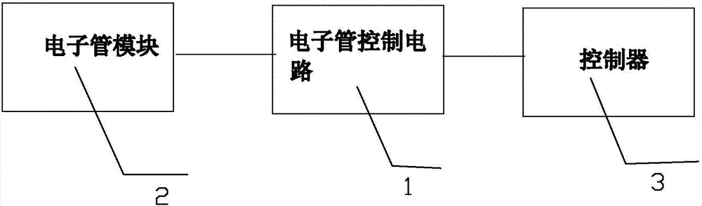
[0010] like figure 1 As shown, the present invention is composed of an electron tube module 2 , an electron tube control circuit 1 and a controller 3 .

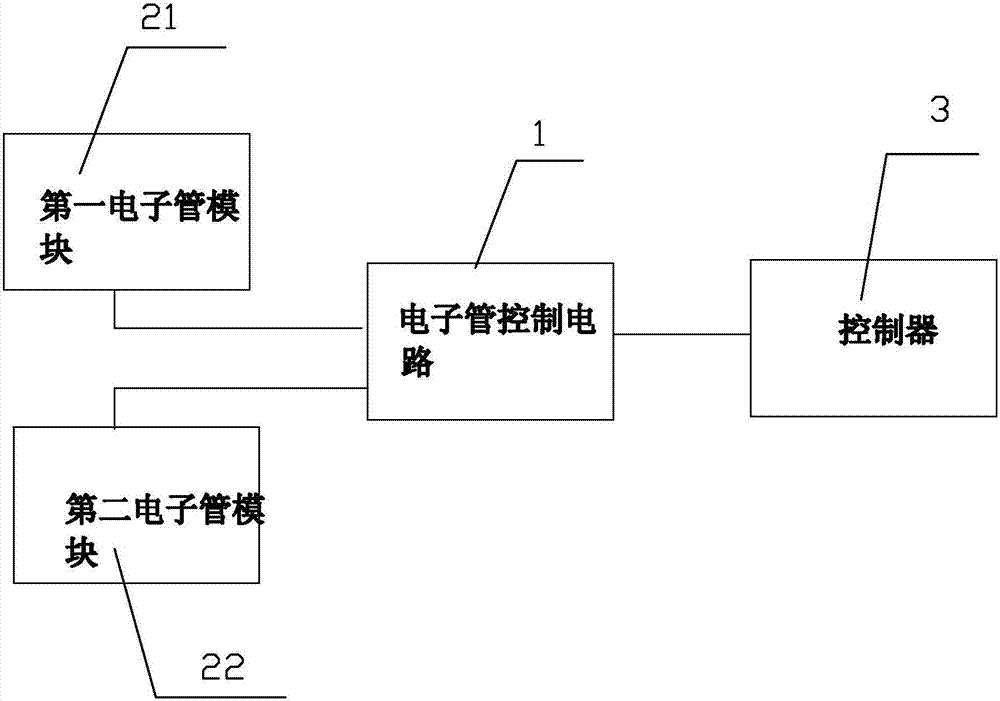
[0011] like figure 2 As shown, in a specific embodiment of the present invention, the electron tube module 2 is composed of a first electron tube 21 and a second electron tube 22, the first electron tube 21 and the second electron tube 22 are common electron tube circuit structures, and are composed of a filter circuit and an oscillation circuit configuration. The first electron tube 21 and the second electron tube 22 each include a coil, the coil of the first electron tube 21 is wound around a first central axis, and the coil of the second electron tube 22 is wound around a second central axis. Since they are placed on the same printed circuit board, in order...


PUM


Abstract

A linear electron beam tube adopts a programmable logic controller to precisely control the working current of a high-frequency welding machine. By setting a sampling resistor in the cathode circuit of the high-frequency oscillating tube of the fusion splicer, the voltage drop on the resistor is input to PLC or MCU, and the CPU in it calculates the cathode current value I according to Ohm's law. ca , the cathode current value I ca with the preset current value I ref The comparison is performed, and the compared difference is used to control the mechanical action of the high-frequency welding equipment. The method and the circuit designed according to the method can accurately control the high-frequency output current of the high-frequency welding equipment, and greatly improve the qualified rate of welded products of the high-frequency welding machine. At the same time, the design, installation and commissioning workload of the high-frequency fusion splicer using PLC or MCU is simple, the wiring circuit is simplified, the maintenance workload of the equipment is small, the maintenance is convenient, and the failure frequency of the equipment is further reduced.

Description

technical field [0001] The invention relates to an electronic tube, in particular to an electronic segmented electronic tube. Background technique [0002] At present, fluorescent lamps are widely used because of their energy saving and good luminescence, while electronic tubes are an indispensable device for daylight lighting. When starting (the moment when the starter is disconnected), the electronic tube will generate a higher self-inductance potential superimposed on the power supply voltage, so that the two ends of the lamp tube will get a higher starting voltage; after starting, it will act as a resistor The current coil is connected in series with the lamp tube so that the voltage across the lamp tube is reduced to the rated value. Ring tube fluorescent lamps are generally spliced ​​by several sections of fluorescent tubes. The existing electronic tubes are difficult to realize the conversion and control between multiple lamp tubes. Tube electronics Segmented tubes....

Claims


Application Information

Patent Timeline
Patent Type & Authority Applications(China)
IPC IPC(8): H05B41/14
Inventor 刘新梅
Owner 刘新梅
Why Eureka
Try Eureka