Well jet device and the operating method thereof

a technology of a well jet and an operating method, which is applied in the field of pumping units, can solve the problems of narrowing its operating method, and not fully using the capabilities of the well jet device, so as to improve work reliability, increase the quality of work, and increase the production rate of wells

Inactive Publication Date: 2010-03-30
KHOMYNETS ZINOVIY DMITRIEVICH
View PDF8 Cites 26 Cited by
  • Summary
  • Abstract
  • Description
  • Claims
  • Application Information

AI Technical Summary

Benefits of technology

[0008]The objective of this invention is to raise quality of works on increasing well production rates due to improving technologies of treating producing formation with liquid agents.
[0009]The technical effect achieved by realizing this invention is improvements in work reliability and the well jet device capacity when treating a producing formation.
[0012]A conducted analysis of the well jet device operation has shown that the device operation reliability and efficiency may be increased by optimizing the device design and, thereby, it becomes possible to clean near-well areas of producing formations in wells more fully and to shorten time required for conducting such operations.
[0013]It has been found that hydrodynamic influence on the near-well area enables to use the well jet device most efficiently while developing and repairing oil and gas wells in the course of works on intensifying oil inflow from a producing formation. The inventive well jet device enables to take check measurements both before and during treatment, which, in its turn, enables to assess the technical condition of a well and properties of a medium pumped out of a well. After studying an inflow it becomes possible to assess quality of treatment of the near-well area of a producing formation. Making the well jet device with a working medium flow switch in the form of a supporting sleeve spring-loaded against the body enables treating of a producing formation by injecting chemical agents and / or a hydrofracturing fluid. Such a supporting sleeve closes the channels for supplying a working medium and a pumped-out medium, thus preventing them from plugging. Making a supporting sleeve with a mounting seat enables to install various technological equipment into the sleeve and conduct hydrodynamic treatment of a producing formation as well as make measurements, including recording of a formation pressure recovery curve for the under-packer area, as well as create stepwise pressure drawdown on a producing formation and clean it from mud particles and products of a reaction after treating a producing formation with chemical agents. Thus, it becomes possible to increase a radius and quality of treatment of the producing formation near-well area, while significantly equalizing the inflow profile due to a fuller coverage of such a producing formation throughout its depth with hydrodynamic action.

Problems solved by technology

However, the capabilities of the well jet device are not used in full due to long times required for replacing inserts, wherein such time is often longer than estimated time of the reaction between an acid solution and minerals of a producing formation.
However, the flow switch used creates significant hydraulic resistance and occupies the flow section of the pipe string, which does not enable to lower equipment and various instruments, e.g., measuring instruments, flexible tubes for injecting chemical agents or a hydrofracturing fluid in a formation, and instruments used for acting on formations, into a well, which narrows the capabilities of this well jet device and those of its method of operation.

Method used


Image

  • Well jet device and the operating method thereof
  • Well jet device and the operating method thereof
  • Well jet device and the operating method thereof

Examples


Embodiment Construction

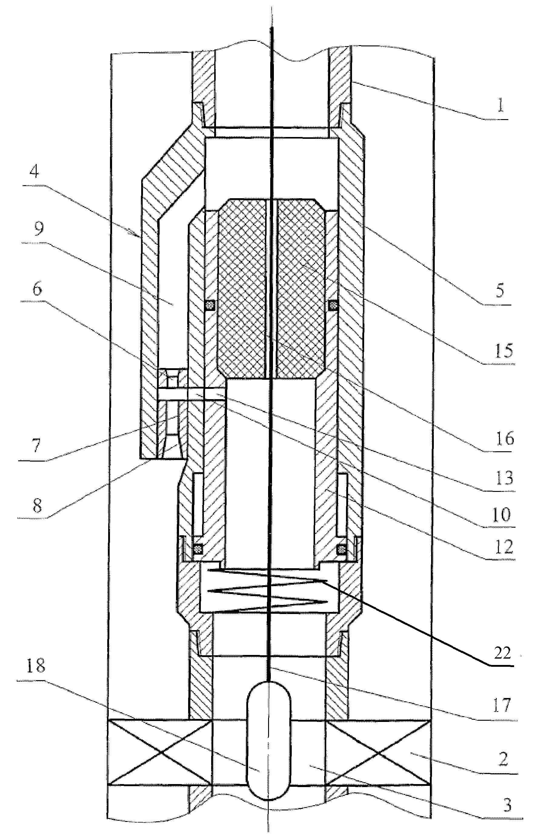
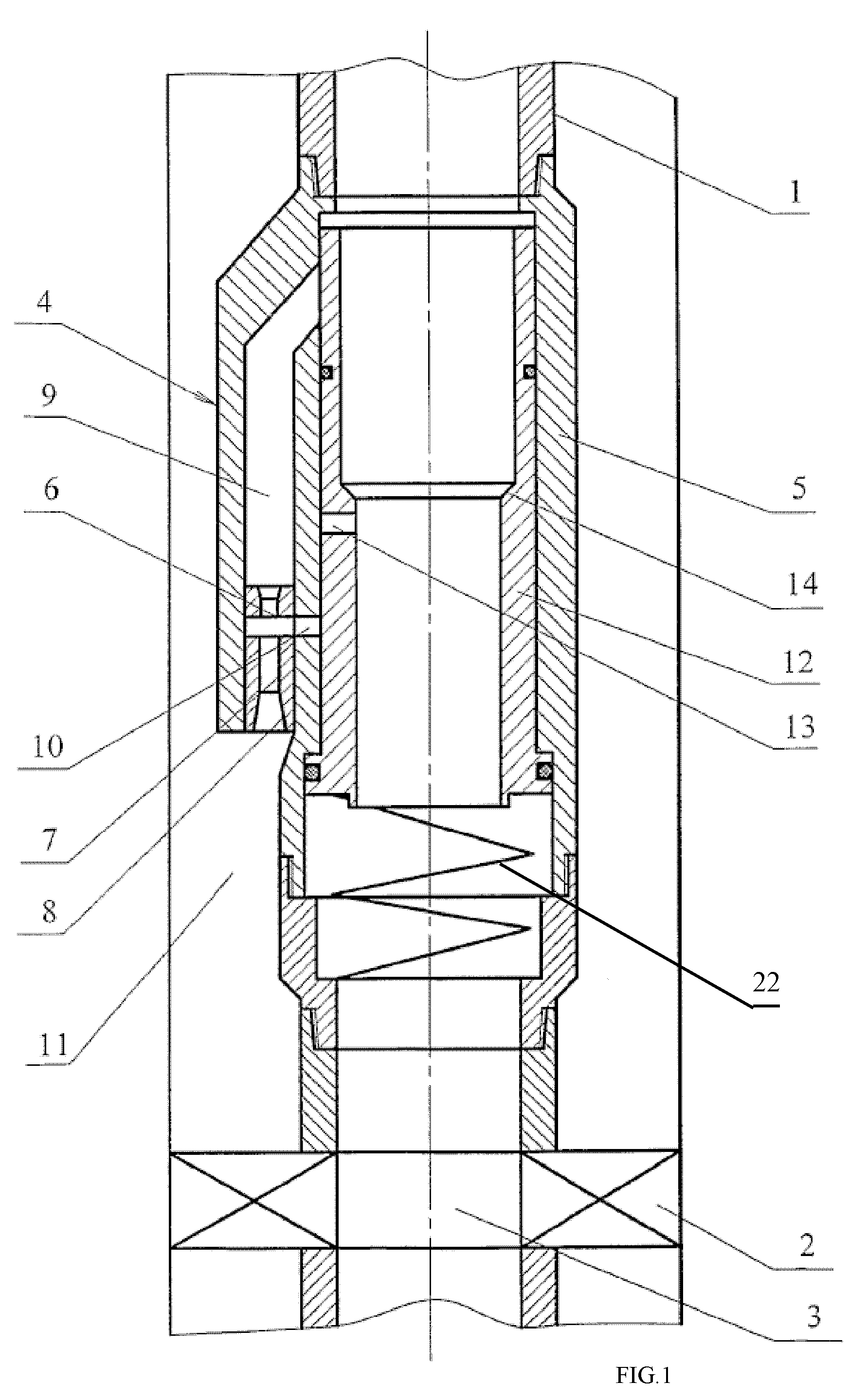
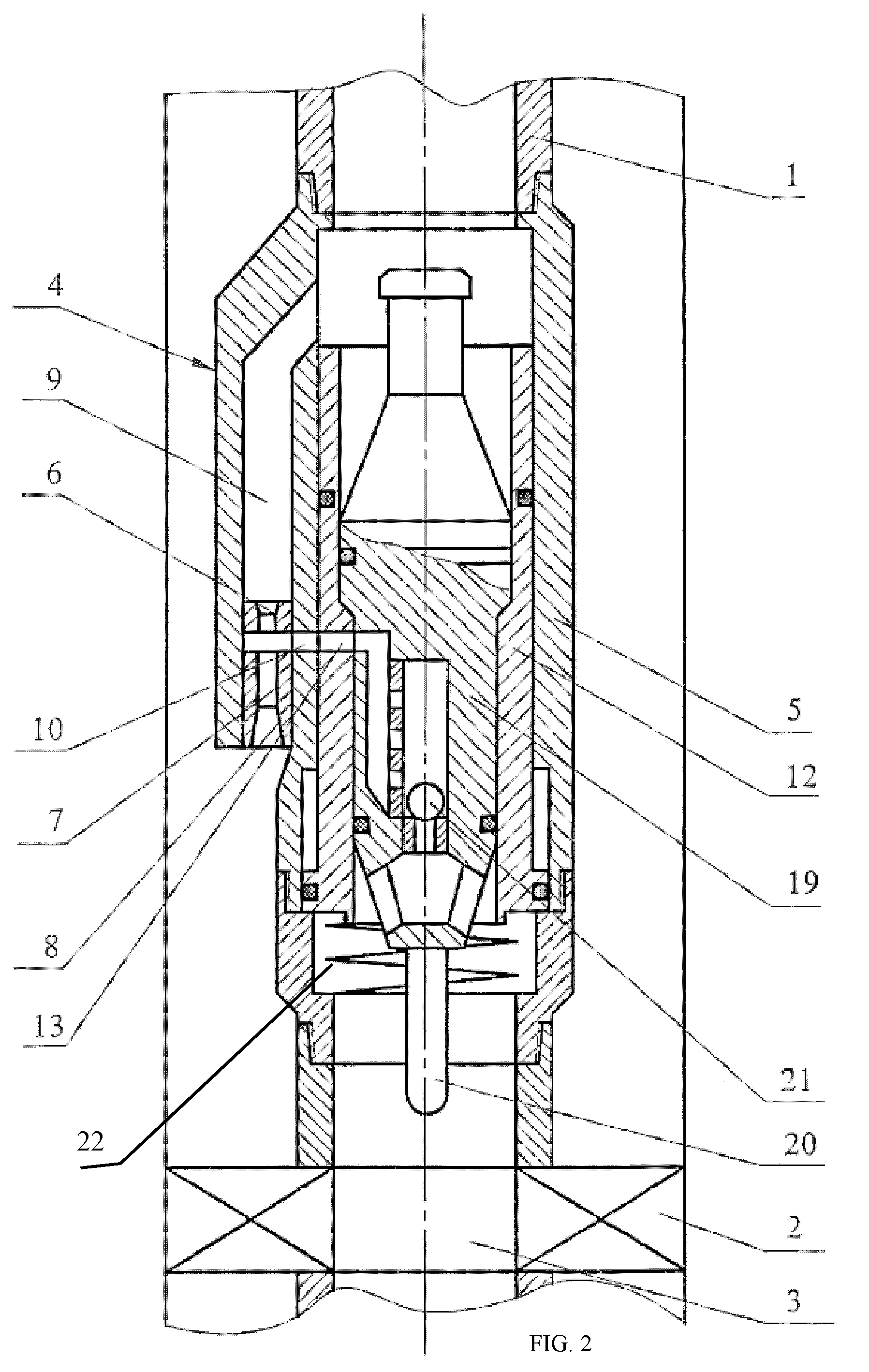
[0017]The inventive well jet device comprises, arranged on a pipe string 1 from bottom to top, a packer 2 with a central channel 3 defined therein defined therein and a jet pump 4, which body 5 comprises a nozzle 6 and a mixing chamber 7 with a diffuser 8 as well as a channel 9 for supplying a working medium to the nozzle 6 and a channel 10 for supplying a medium pumped out of a well. The output of the diffuser 8 is connected to the annular space 11 surrounding the pipe string 1, and the nozzle 6 of the jet pump 4, through the channel 9 for supplying a working medium, and the input of the channel 10 for supplying a medium pumped out of a well are connected to the inner cavity of the pipe string 1. A working medium flow switch is installed in the body 5 of the jet pump 4 coaxially with the pipe string 1, the switch being made as a supporting sleeve 12 axially movable and spring-loaded by spring 22 against the body 5. The supporting sleeve 12 has bypass openings 13 and a mounting seat...


PUM


Abstract

Well jet device comprises a packer on a pipe string, with a central channel and a jet pump, comprising channels for supplying a working medium to a nozzle and supplying a medium pumped from the well. A diffuser output connects to the annular space and the nozzle connects to the pipe string internal cavity on the side of the input thereof through the channels. The body has a movable steady bush, spring-loaded working medium flow switch. Steady bush bypass holes and mounting seat for mounting a sealing unit provided with a hole for passing a logging cable or for arranging a depression insert provided with autonomous instruments and a return valve are provided. The sleeve, in the top position, closes the channels and, in lower position, the top end face is positioned under the input into the channel. The bypass holes are connected to the input into the channel.

Description

FIELD OF THE INVENTION[0001]This invention relates to pump engineering, primarily to well pump units used in testing and developing oil and gas wells.PRIOR ART[0002]A well jet device is known, which comprises, arranged on a pipe string from bottom to top, a packer with a central channel defined therein and a jet pump, the jet pump body comprising an active nozzle and a mixing chamber with a diffuser as well as a channel for supplying a working medium and a channel for supplying a medium pumped out of a well, wherein the jet pump body is provided with a through channel for the purpose of installing replaceable functional inserts and a sealing unit therein (RU 2176336 C1).[0003]The same patent teaches a method of operating a well jet device, including arranging a jet pump on a flow string in a well and pumping chemical agents via the flow string into a formation subject to subsequent pumping reaction products out of the formation, wherein a blocking insert with a through channel is fi...

Claims


Application Information

Patent Timeline
Patent Type & Authority Patents(United States)
IPC IPC(8): E21B47/00F04F5/54
CPCE21B43/124F04F5/464
Inventor KHOMYNETS, ZINOVIY DMITRIEVICH
Owner KHOMYNETS ZINOVIY DMITRIEVICH
Why Eureka
Try Eureka