
Metallic arrow shaft with fiber reinforced polymer core

a fiber reinforced polymer core and arrow shaft technology, applied in the field of arrow systems, can solve the problems of low circumferential or the arrows cannot withstand, and the hoop strength of the arrow shaft is so low

Inactive Publication Date: 2010-03-30
EASTON TECHN PRODS
View PDF31 Cites 15 Cited by
  • Summary
  • Abstract
  • Description
  • Claims
  • Application Information

AI Technical Summary

Benefits of technology

"The present invention provides an improved arrow shaft design that includes a metallic layer over an FRP core, resulting in a stronger and more durable shaft. The metallic layer can be made of aluminum or metal alloy and is adhered to the FRP core using an adhesive. The shaft also includes an insert for attaching a point, and a nock for securing the other end. The hybrid arrow structure includes a thin walled tube of carbon fiber composite and a thin walled tube of aluminum alloy, with an adhesive bond between them. The method of making the arrow shaft involves placing the metallic jacket over the FRP tube, adhering it to the FRP tube, and attaching the point and nock to the FRP tube."

Problems solved by technology

Prior designs and processes for constructing FRP shafts resulted in a low circumferential or hoop strength.
The hoop strength of these arrow shafts was so low that the arrows could not withstand even small internal loads applied in a direction radially outward from the center of the shaft.
For example, internal loads generated from inserting standard components into the inside of these types of shafts would likely have resulted in failure of the arrow shaft.
Such higher velocities result in a flatter arrow trajectory.
Nevertheless, FRP and ACC arrows have a number of significant drawbacks.
This makes FRP and ACC arrows difficult to pull from the target.
The FRP and ACC arrows may also be damaged as a result of the forces required to remove them from targets.

Method used


Image

  • Metallic arrow shaft with fiber reinforced polymer core
  • Metallic arrow shaft with fiber reinforced polymer core
  • Metallic arrow shaft with fiber reinforced polymer core

Examples


Embodiment Construction

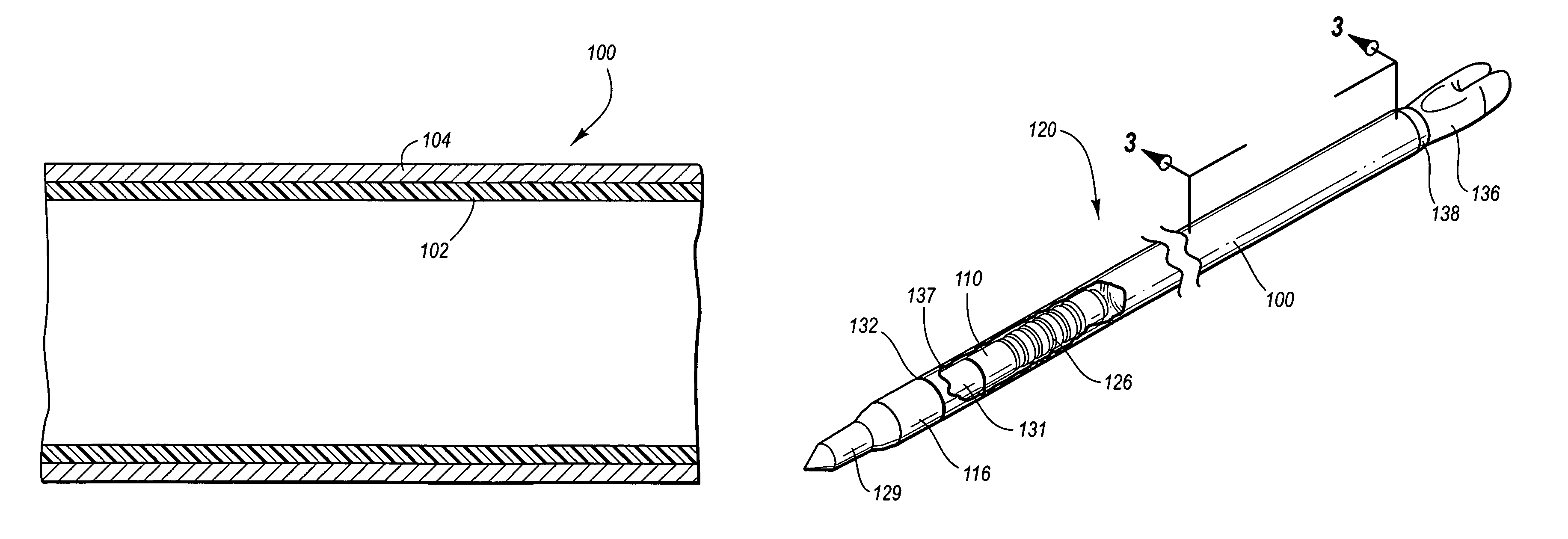
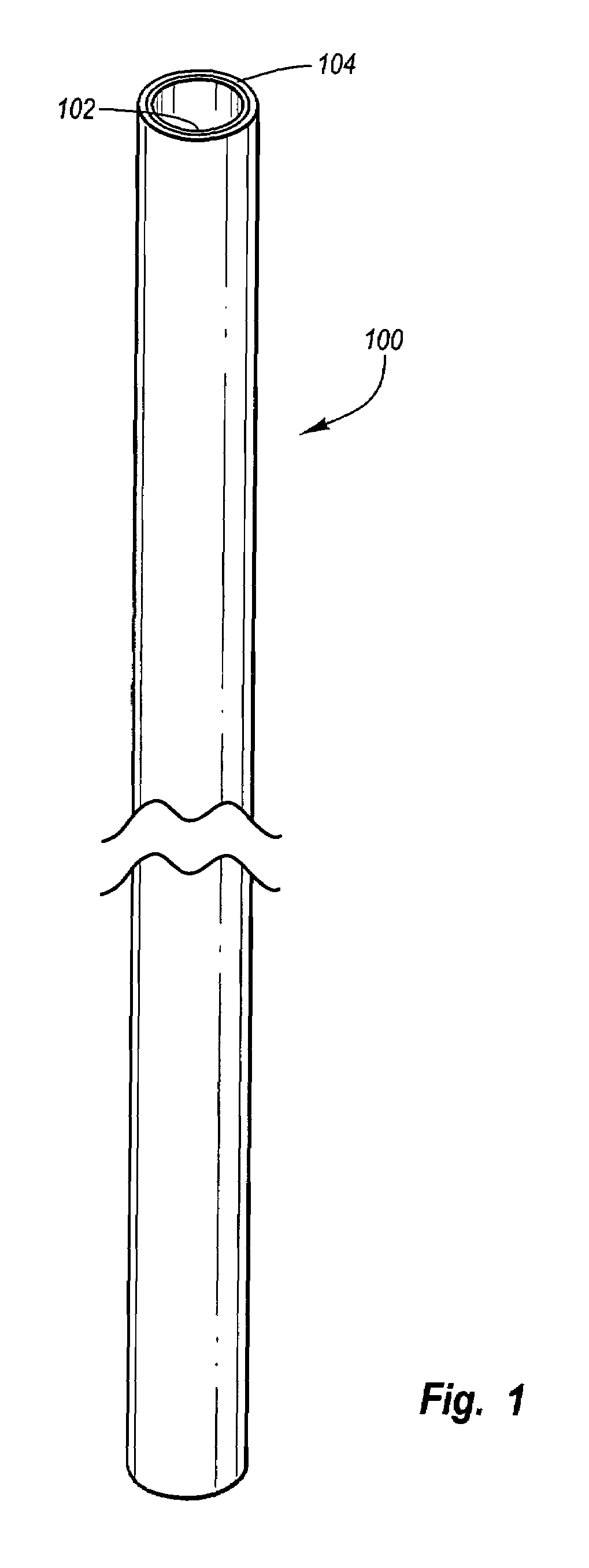
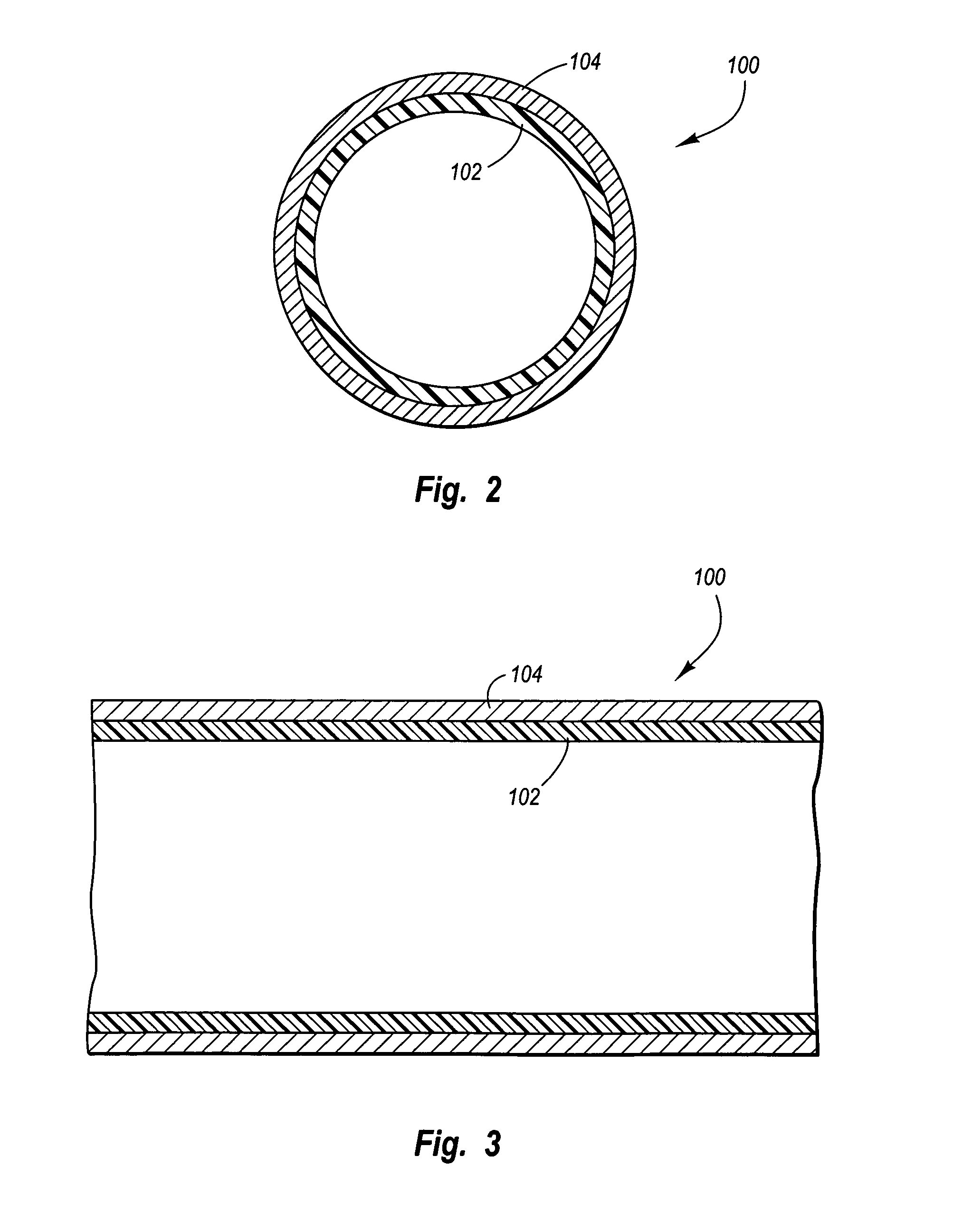
[0018]The present specification describes a novel shaft and arrow system that may be used for archery, and particularly for bowhunting and target shooting. One aspect of the novel arrow shaft relates to an arrow with an inner FRP structure, and an outer metal jacket or layer. The outer metal jacket provides resistance to deformation and damage, and provides an arrow shaft structure that is more durable than conventional all-carbon composite designs. The outer metal jacket protects against or resists splitting of the FRP structure. The outer metal jacket may be finished with a camouflage pattern with no additional weight of significance. Shafts made of all-carbon composite, on the other hand, have a weight gain associated with the amount of extra material required to add the camouflage pattern. The hybrid structure disclosed herein with an inner FRP and an outer metal jacket can be straightened to very precise tolerances. In contrast, all-carbon composite arrow shafts are generally s...


PUM


Abstract

The present invention is directed to a shaft and arrow system. The shaft and arrow system includes a hybrid structure that may include two concentric tubes. A first of the two concentric tubes may comprise an outer shell or jacket of thin-walled metal alloy. A second of the two concentric tubes may include an inner core of thin-walled fiber reinforced polymer. The two concentric tubes may be bonded together by a suitable adhesive such as epoxy or urethane. The shaft may have a reduced diameter as compared to conventional arrow shafts, and the shaft may be receptive of a variety of inserts, points, nocks, and other components. Some inserts may be completely recessed within a first end of the shaft.

Description

TECHNICAL FIELD[0001]This invention relates to arrow systems, including in particular hunting and target arrow systems.BACKGROUND OF THE INVENTION[0002]Many different types of arrows and arrow shafts are known for use in hunting and sport archery. Two arrow types of relatively recent design are the fiber reinforced polymer (FRP) arrows and the aluminum arrows wrapped with fiber reinforced polymer. FRP is a generic term including, but not limited to, fiberglass composites and carbon fiber composites. Aluminum arrow shafts covered with FRP are usually made of an aluminum core covered with carbon fiber and are often referred to as aluminum carbon composite (ACC) arrows, although any FRP may be used as the covering. Traditional FRP and ACC shafts have been produced by a number of different manufacturing processes. The first FRP arrow shafts were constructed with unidirectional reinforcing fibers aligned parallel to the axis of the shaft.[0003]Prior designs and processes for constructing...

Claims


Application Information

Patent Timeline
Patent Type & Authority Patents(United States)
IPC IPC(8): F42B6/04
CPCF42B6/04A63B2244/04
Inventor SMITH, JACOB C.ROWSELL, EDWIN A.PALOMAKI, TEDDY D.
Owner EASTON TECHN PRODS
Learn More