Thermally controlled fluidic self-assembly

a technology of fluidic self-assembly and fluidic micro-assembly, which is applied in the direction of microstructured devices, microstructured technology, instruments, etc., can solve the problems of high cost of providing the array of disks on the substrate, the inability to provide the discrimination useful in the assembly of components having multiple types of micro-components, and the inability to apply deterministic methods in a cost effective manner. , to achieve the effect of increasing

Inactive Publication Date: 2010-03-30
EASTMAN KODAK CO
View PDF32 Cites 56 Cited by
  • Summary
  • Abstract
  • Description
  • Claims
  • Application Information

AI Technical Summary

Problems solved by technology

Accordingly, such deterministic methods are difficult to apply in a cost effective manner.
However, it will be appreciated that this method requires the precise placement of drops of liquid 34 on substrate 10 and does not necessarily provide the discrimination useful in the assembly of components having multiple types of micro-components.
However, high cost is encountered in providing the arrays of disks on the substrate.
Further such methods are typically limited to applications wherein the micro-assembled structures being assembled each have magnetic characteristics that permit the use of magnetic forces in this fashion.
However, the use of electrostatically based fluidic micro-assembly can involve high cost associated with providing addressable electrode structures required for long range transport of micro-components by dielectrophoresis.
However, the constraints of surface etching techniques, micro-component formation techniques, cost, electrical function, and orientation limit the number of shape configurations that are available for use in discrimination, which in turn limits the number of different components that can be placed on the substrate using such a process.
While this approach provides a high degree of differentiation high cost may be encountered in patterning the DNA or ligands on the substrate.

Method used


Image

  • Thermally controlled fluidic self-assembly
  • Thermally controlled fluidic self-assembly
  • Thermally controlled fluidic self-assembly

Examples


Embodiment Construction

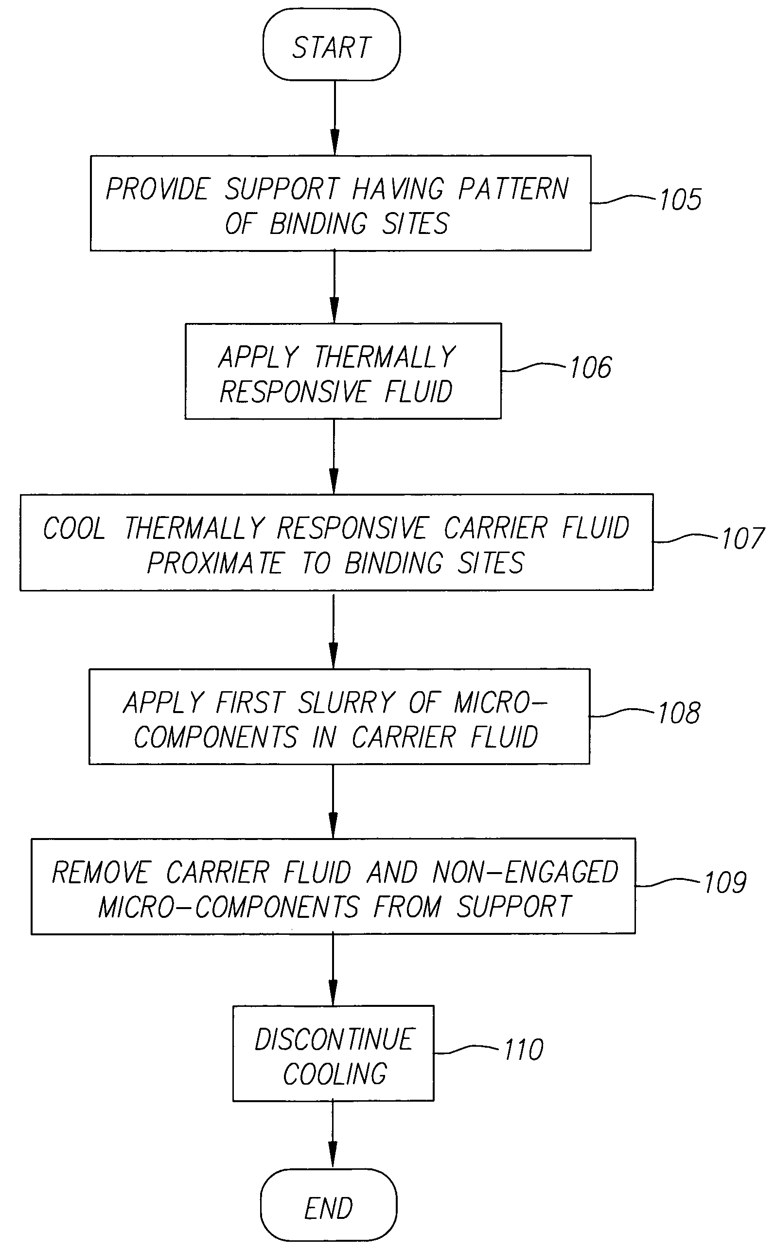
[0039]FIG. 2A is a flow diagram of one embodiment of the method of invention. FIGS. 3A and 3B illustrate one example of fluidic self-assembly in accordance with the method of FIG. 2A. As is shown in FIG. 3A, a support 60 is provided (step 105). Support 60 can be, but is not limited to, a flexible support such as polyethylene terephthalate, cellulose acetate, polyethylene, polycarbonate, polymethyl methacrylate, polyethylene napthalate, metal foils, cloth, fabric, woven fiber or wire meshes or rigid supports such as glass and silicon.

[0040]Support 60 has pattern of binding sites shown in FIGS. 3A-3C as binding sites 62, 64, 66 and 68. Each binding site 62, 64, 66 and 68 is adapted so that a micro-component can be assembled thereon, such as by shaping binding sites 62, 64, 66 and 68 to receive the micro-component. Alternatively, support 60 can have binding sites 62, 64, 66 and 68 that are adapted to engage micro-components using, for example, shape matching, magnetic force, electrical...


PUM

PropertyMeasurementUnit
viscosityaaaaaaaaaa
hydrophobicaaaaaaaaaa
gel transition temperatureaaaaaaaaaa

Abstract

Methods and apparatuses are provided for assembling a structure on a support having a pattern of binding sites. In accordance with the method, a first fluid is provided on the surface of the support with the first fluid being of a type that that increases viscosity when cooled, the first fluid having first micro-components suspended therein each adapted to engage the binding sites. First fluid proximate to selected binding sites is cooled to increase the viscosity of the responsive fluid proximate to the selected binding sites so that the first micro-components suspended in the first fluid are inhibited from engaging the selected binding sites.

Description

CROSS-REFERENCE TO RELATED APPLICATIONS[0001]Reference is made to commonly assigned, co-pending patent application U.S. Ser. No. 10 / 849,302, entitled THERMALLY CONTROLLED FLUIDIC SELF-ASSEMBLY METHOD AND SUPPORT, filed Sep. 3, 2004 in the names of Daniel D. Haas et al.; and U.S. Ser. No. 10 / 849,329, entitled THERMALLY CONTROLLED FLUIDIC SELF-ASSEMBLY AND CONDUCTIVE SUPPORT, filed Sep. 3, 2004 in the names of Theodore K. Ricks et al.FIELD OF THE INVENTION[0002]The present invention relates to methods for fluidic micro-assembled structure and, in particular, to methods and apparatuses for selective fluidic assembly of micro-components.BACKGROUND OF THE INVENTION[0003]Micro-assembled devices offer the promise of an entirely new generation of consumer, professional, medical, military, and other products having features, capabilities and cost structures that cannot be provided by products that are formed using conventional macro-assembly and macro-fabrication methods. For example, there ...

Claims


Application Information

Patent Timeline
Patent Type & Authority Patents(United States)
IPC IPC(8): G01N33/00B81C99/00
CPCH01L24/86H01L25/50H01L24/95Y10T436/25H01L2224/95085H01L2224/95136H01L2224/95144H01L2224/95145H01L2924/01013H01L2924/01015H01L2924/01027H01L2924/01074H01L2924/10329H01L2924/14H01L2924/15155H01L2924/15165H01L2924/19041H01L2924/19042H01L2924/19043H01L2924/3025H01L2224/83192H01L2924/01005H01L2924/01006H01L2924/01019H01L2924/01033H01L2924/12041H01L2924/15153H01L2924/12042H01L2924/00
Inventor SHARMA, RAVILUSIGNAN, CHARLES P.
Owner EASTMAN KODAK CO
Why Eureka
Try Eureka