Magnetic heads disk drives and methods with floating pole tip or shunted pole tip for reduced pole tip erasure

a technology of magnetic head and disk drive, which is applied in the field of magnetic head write head, can solve the problems of pole tip inadvertently changing the magnetization state of other bits on the disk drive, catastrophic failure of the disk drive, and pole tip shape anisotropy

Inactive Publication Date: 2010-03-30
SEAGATE TECH LLC
View PDF11 Cites 14 Cited by
  • Summary
  • Abstract
  • Description
  • Claims
  • Application Information

AI Technical Summary

Benefits of technology

[0015]Embodiments of the present invention relate generally to disk drive write heads with designs that minimize the effects of pole-tip erasure caused by remnant magnetic fields in the write yoke or the write pole tip.
[0016]A disk drive according to a general embodiment of the present invention comprises a write shield, a write return yoke connected to the write shield, a write yoke connected to the write return yoke, conductive coils surrounding the write yoke, a write pole tip, and a spacer connecting the write pole tip to the write yoke. The conductive coils surrounding the write yoke induce a magnetic field in the write yoke when an electric current passes through the conductive coils. The spacer connecting the write pole tip and the write yoke prevents a magnetization of the write pole tip when there is a small remnant magnetic field in the write yoke.

Problems solved by technology

A problem occurs when the magnetic state of the pole tip does not return to zero magnetization when the current in the conductive coils of the write head is stopped.
This causes the pole tip to maintain some remnant magnetization field; and, as the write head moves across the disk, the pole tip can inadvertently change the magnetization state of other bits on the disk.
Pole tip erasure (PE) can corrupt the data stored on the disk, and cause catastrophic failure for the disk drive.
One possible cause is the shape anisotropy of the pole tip.
Another possible cause of remnant magnetization in the pole tip is domain lockup of the yoke.
Both methods proposed by Bai and Zhu are extremely difficult to manufacture in a manufacturing production process.
The insertion of a gap with such dimensions and aspect-ratio cannot be practically achieved in a manufacturing process using the current state-of-the-art manufacturing techniques.
Such a process step is expensive, time-consuming, difficult to control, and incompatible with electroplating manufacturing processes.

Method used


Image

  • Magnetic heads disk drives and methods with floating pole tip or shunted pole tip for reduced pole tip erasure
  • Magnetic heads disk drives and methods with floating pole tip or shunted pole tip for reduced pole tip erasure
  • Magnetic heads disk drives and methods with floating pole tip or shunted pole tip for reduced pole tip erasure

Examples


Embodiment Construction

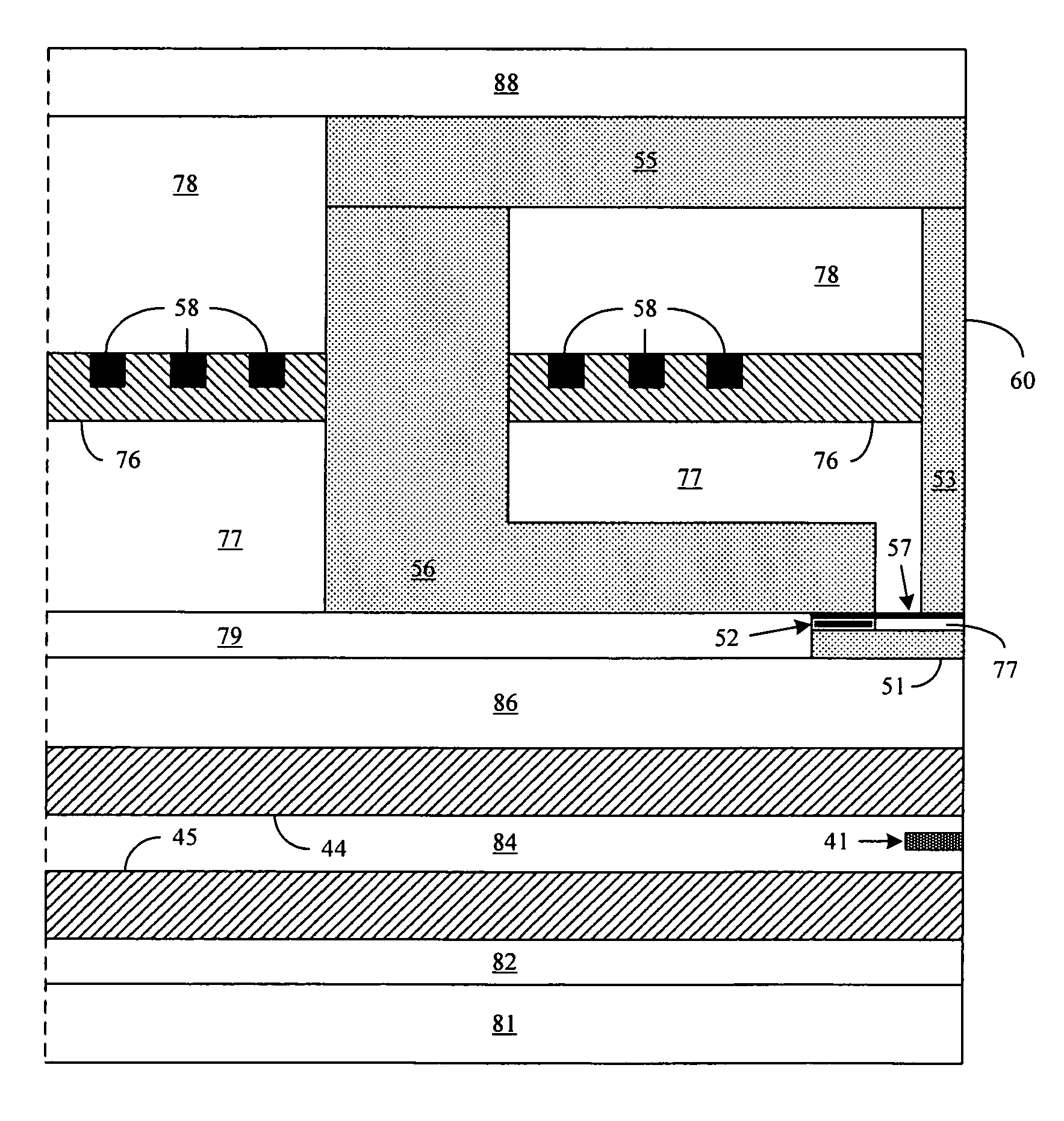
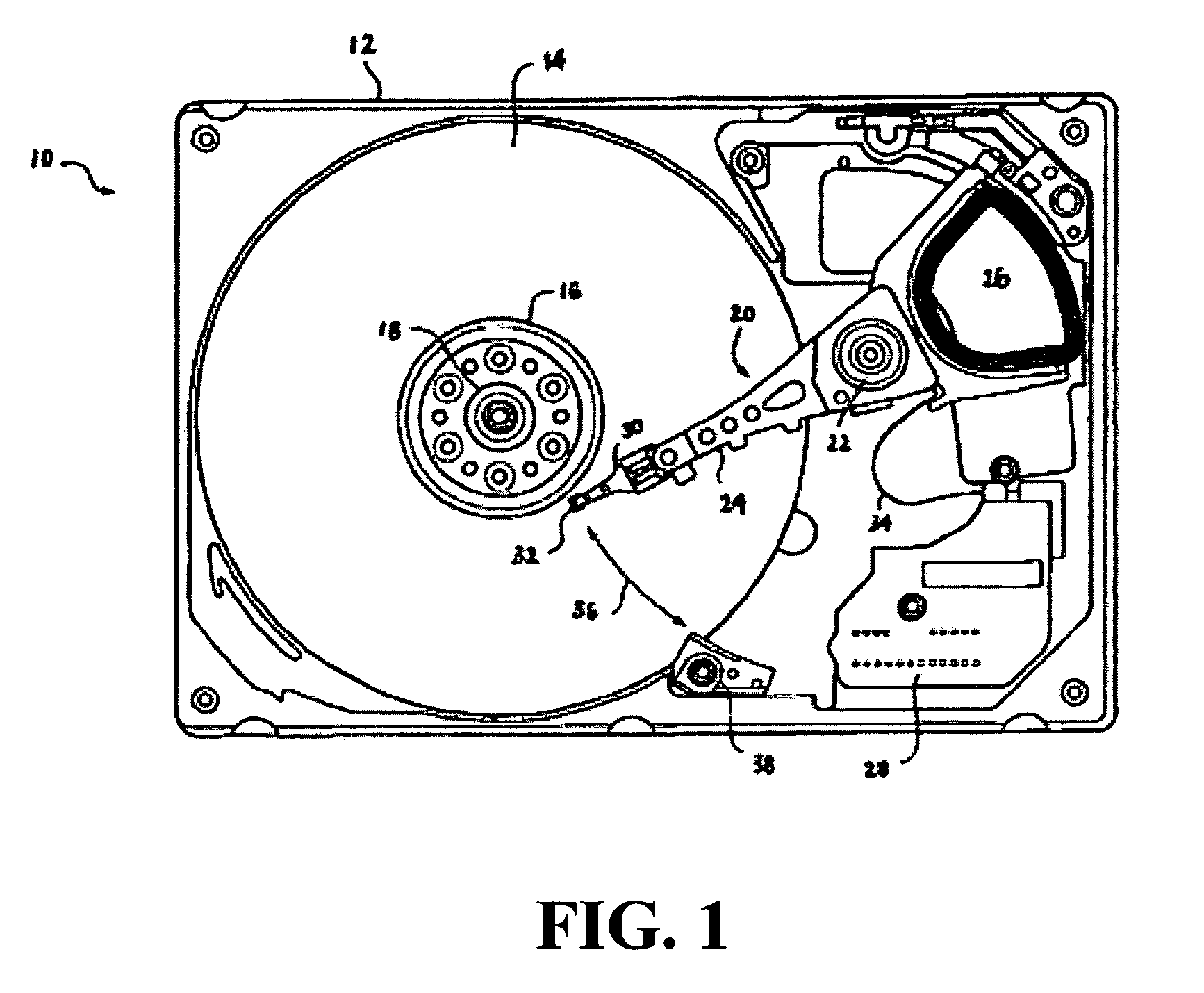
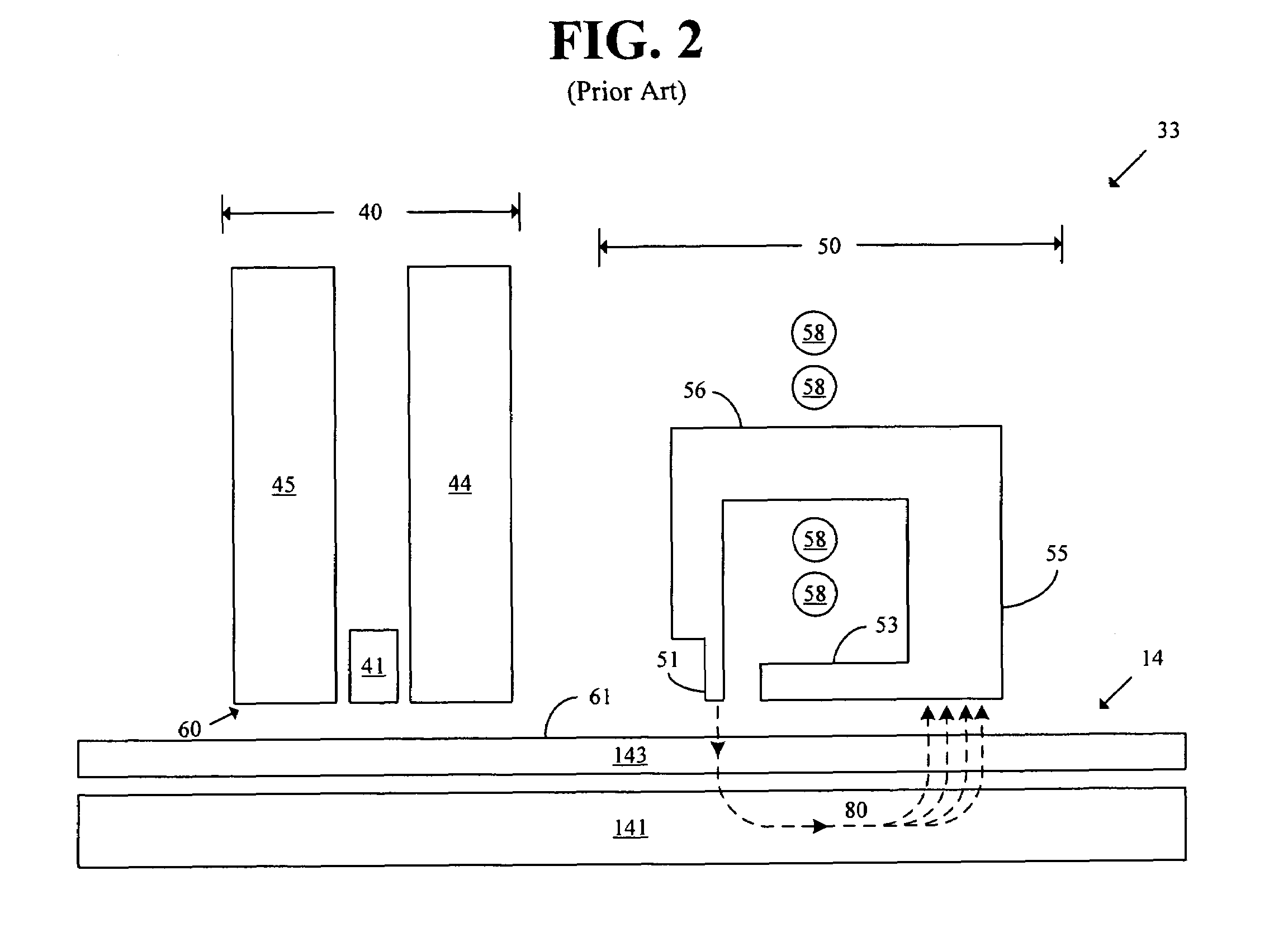
[0043]Reference will now be made to the accompanying drawings, which assist in illustrating the various pertinent features of the present invention. Although the present invention will now be described primarily in conjunction with disk drives, it should be expressly understood that the present invention may be applicable to other applications where magnetic recording of data is required / desired. In this regard, the following description of a disk drive is presented for purposes of illustration and description. Furthermore, the description is not intended to limit the invention to the form disclosed herein. Consequently, variations and modifications commensurate with the following teachings, and skill and knowledge of the relevant art, are within the scope of the present invention. The embodiments described herein are further intended to explain best modes known of practicing the invention and to enable others skilled in the art to utilize the invention in such, or other embodiments...


PUM

PropertyMeasurementUnit
magnetic fieldaaaaaaaaaa
magnetic fluxaaaaaaaaaa
non-magneticaaaaaaaaaa

Abstract

A write head includes a write return yoke, a write yoke connected to the write return yoke, conductive coils surrounding the write yoke, a write pole tip, and a non-magnetic spacer connecting the write pole tip to the write yoke. The non-magnetic spacer allows for reducing a magnetization of the write pole tip due to a remnant magnetic field in the write yoke. In another embodiment, the write head comprises a write shield, a write return yoke, a write yoke, conductive coils, a write pole tip, and a saturable yoke shunt connecting the write pole tip and the write shield. The saturable yoke shunt directs a limited amount of magnetic flux from the write pole tip to the write shield, such that when there is a remnant magnetic field in the write pole tip, the magnetic flux is directed to the write shield rather than to a disk.

Description

CROSS-REFERENCE TO RELATED PATENT APPLICATIONS[0001]This application claims priority from U.S. Provisional Application Ser. No. 60 / 683,579, filed May 23, 2005, entitled “Reduced Pole Erase with Floating or Shunted Pole Tip”, the contents of which are incorporated by reference herein.BACKGROUND OF THE INVENTION[0002]1. Field of the Invention[0003]The present invention relates generally to disk drive write heads with pole tips that have reduced pole-tip erasure properties, and to methods of manufacturing such write heads.[0004]2. Related Art[0005]Disk drives are used in a wide variety of electronic devices, ranging from personal computers to portable media players, for the storage and retrieval of data. In a disk drive, data is typically written to and read from magnetic storage media called disks. A disk drive typically comprises a plurality of disks for the storage of data and one or more read / write heads for the reading and writing of data. There is a constant market demand to incr...

Claims


Application Information

Patent Timeline
Patent Type & Authority Patents(United States)
IPC IPC(8): G11B5/187
CPCG08B13/19632G08B13/19634G08B13/19643G08B13/19693G08B25/009
Inventor MALLARY, MICHAELBENAKLI, MOURAD
Owner SEAGATE TECH LLC
Why Eureka
Try Eureka