Offshore oil-drilling rig and methods for installing same on an offshore oil-drilling site

Active Publication Date: 2010-04-06
TECH FRANCE SA
View PDF5 Cites 0 Cited by
  • Summary
  • Abstract
  • Description
  • Claims
  • Application Information

AI Technical Summary

Benefits of technology

[0011]The invention is intended to overcome these drawbacks by proposing an offsh

Problems solved by technology

But, given the size of such piles, this measure is a lengthy and costly operation because it requires intervention of heavy equipment whose operating cost is extremely high.
During transportation of the preassembled platform from the erection site to the production site, either by floating the platform or by barge, these caissons, which are several meters high, are in the water and create high resistance to platform forward movement and

Method used


Image

  • Offshore oil-drilling rig and methods for installing same on an offshore oil-drilling site
  • Offshore oil-drilling rig and methods for installing same on an offshore oil-drilling site
  • Offshore oil-drilling rig and methods for installing same on an offshore oil-drilling site

Examples


Example

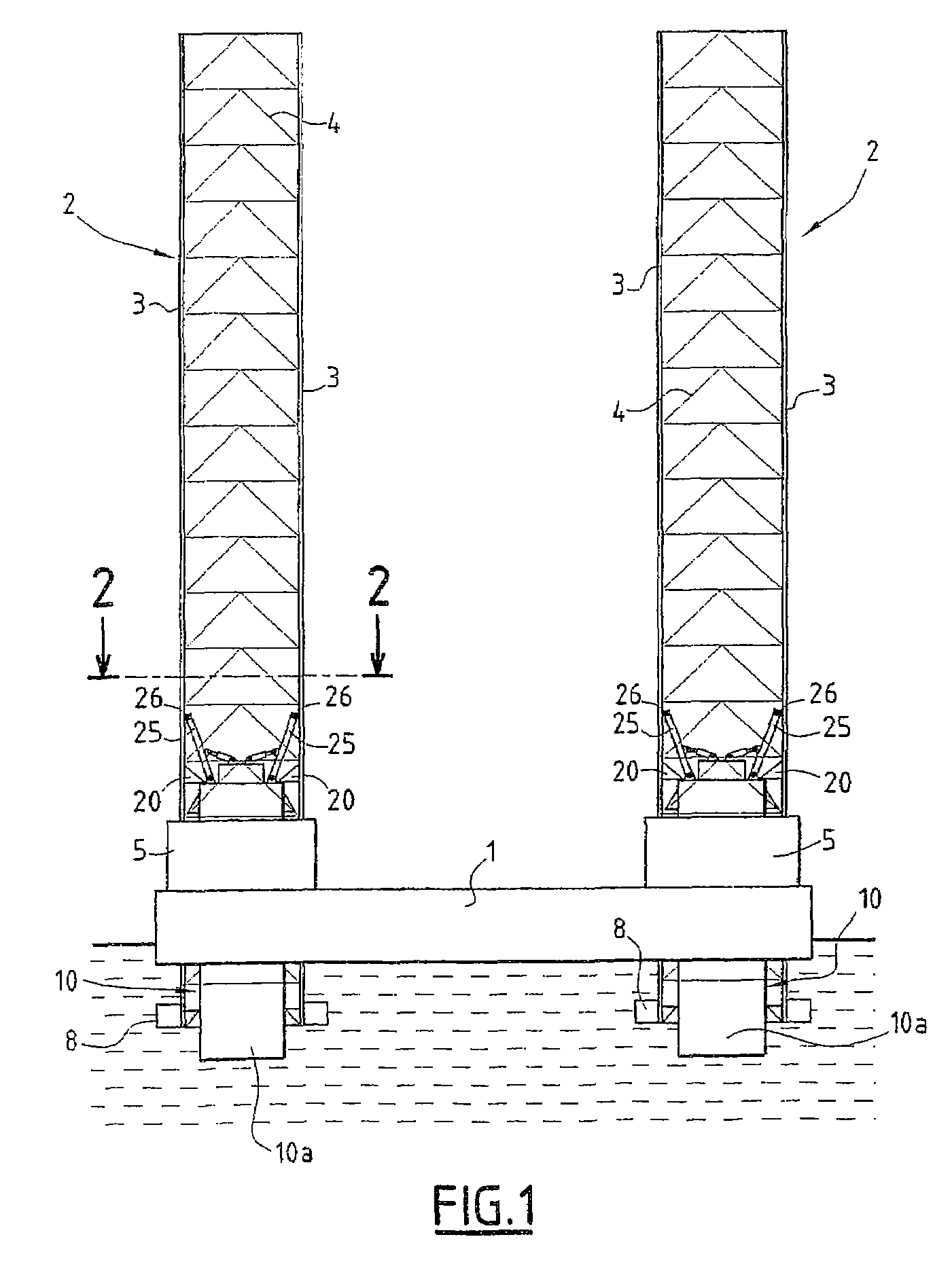
[0041]FIG. 1 illustrates schematically an offshore production, in particular a jackup, platform comprising a deck 1 provided with the usual production equipment and living premises.

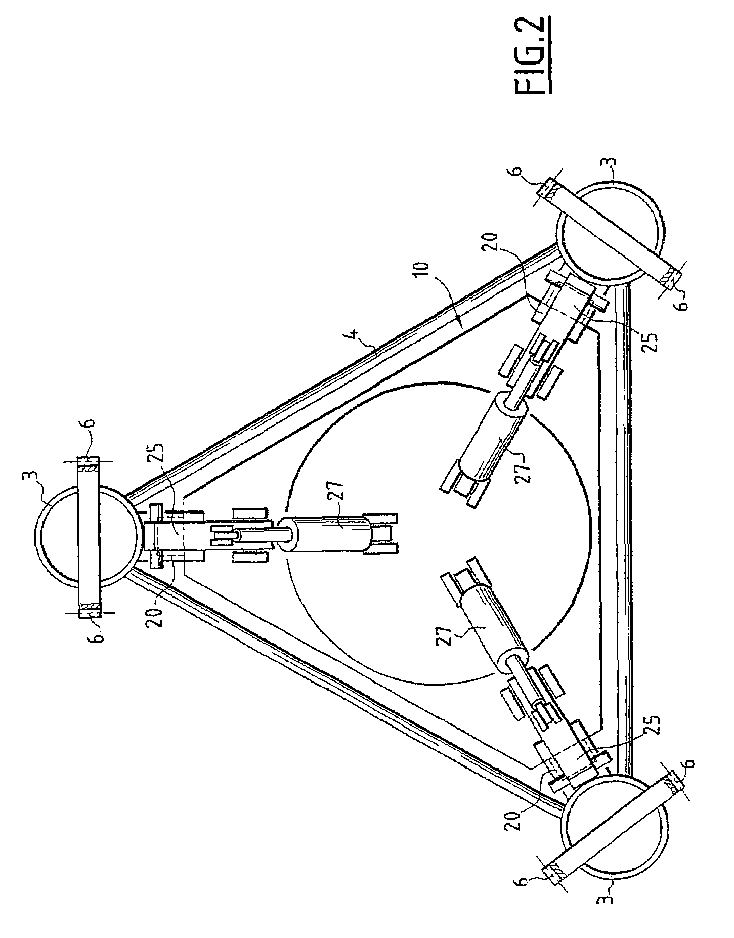
[0042]The deck 1 is moveably mounted on vertical legs 2, each of which is of triangular cross section, as shown in FIG. 2. These legs 2 can also be of square or circular cross section and they can number three or four, spaced uniformly on the deck 1.

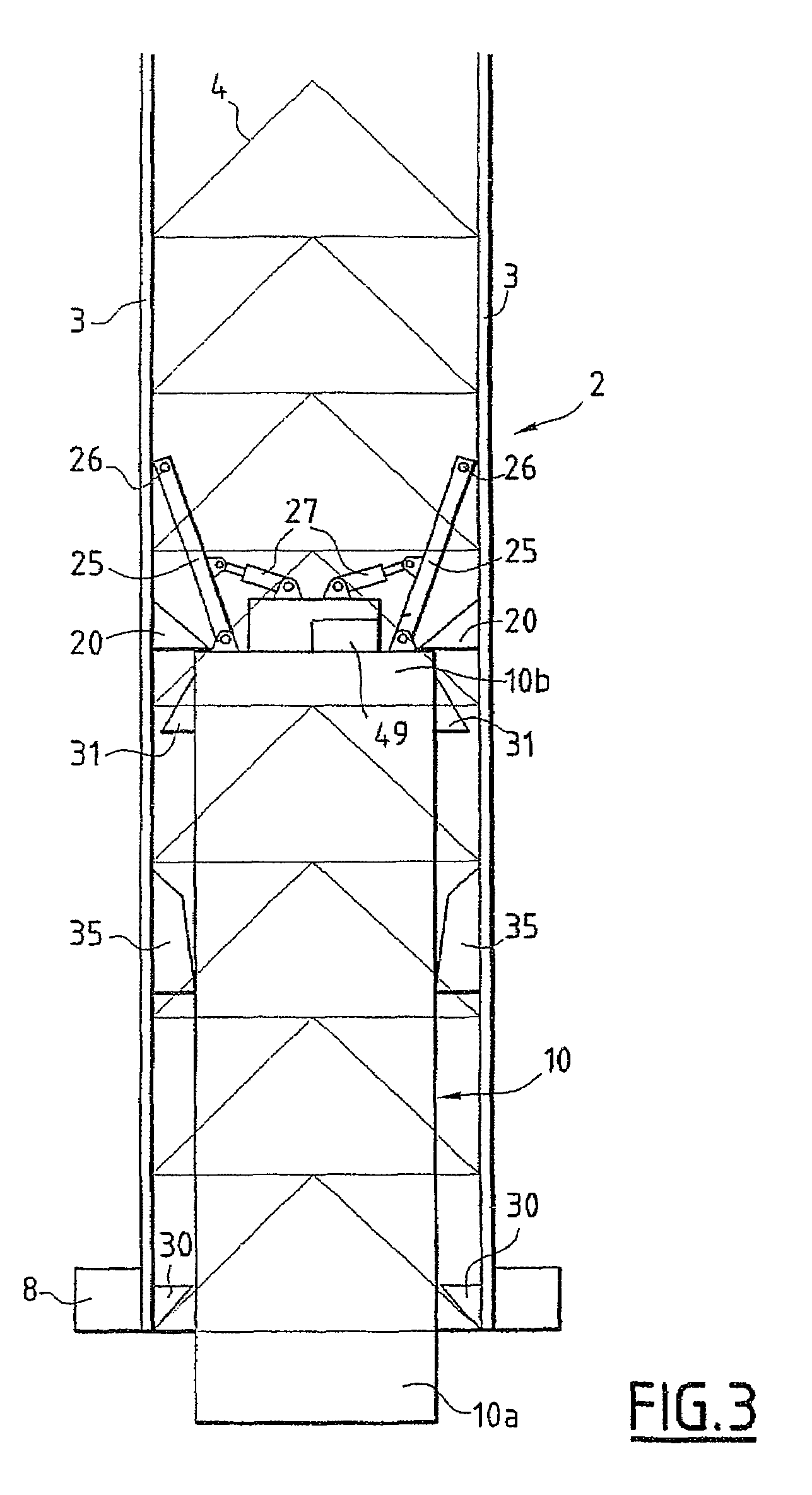
[0043]FIG. 2 shows that each leg 2 is made up of three members 3 interconnected by a lattice of steel struts 4. Only two members 3 are shown in FIGS. 1, 6 and 7 for simplicity.

[0044]Movement of the deck 1 along the legs 2 is performed using drive mechanisms, not represented, located for each leg in a supporting framework 5, also called a “jackhouse” by specialists. Each supporting framework 5 is carried by the deck 1 and the drive mechanisms are conventionally formed of reduction gear units each driving an output pinion cooperating with racks 6 located on the ...


PUM


Abstract

An offshore oil-drilling rig comprising a deck mounted mobile on legs, each leg including a support base on the sea floor and a caisson open at its base and designed to penetrate into the sea floor. Each caisson is arranged inside the leg and is mobile along the axis of the leg between a retracted upper position and a projecting lower position at which it is anchored on the sea floor. The invention also concerns methods for installing such a rig on an oil-drilling site.

Description

CROSS REFERENCE TO RELATED APPLICATION[0001]This is a 35 U.S.C. §§371 national phase conversion of PCT / FR2005 / 002379, filed Sep. 26, 2005, which claims priority of French Application No. 0410545, filed Oct. 6, 2004. The PCT International Application was published in the French language.BACKGROUND OF THE INVENTION[0002]The present invention relates to an offshore production platform and methods of installing such a platform on a production site.[0003]Jackup-type offshore production platforms, such as oil platforms for example, generally comprise legs, usually three in number, bearing on the seabed, and a deck mounted so as to be able to move with an adjustable height on the legs and carrying, in particular, production equipment and living premises.[0004]The bottom end of each leg is fitted with a foot or stand designed to bear on the seabed when the platform is installed on a production site. This foot or stand of each leg provides a limited area of contact with the seabed, allowing ...

Claims


Application Information

Patent Timeline
IPC IPC(8): E02B17/02
CPCE02B17/0818E02B17/021E02B2017/006E02B2017/0078B63B21/50E02B17/00
Inventor THOMAS, PIERRE-ARMANDTCHERNIGUIN, NICOLAS
Owner TECH FRANCE SA
Why Eureka
Try Eureka