Single-mode photonic-crystal VCSELs

a photonic crystal and single-mode technology, applied in the direction of laser cooling arrangements, laser details, electrical equipment, etc., can solve the problems of reducing the yield of devices, and reducing the single-mode operating regime. , to achieve the effect of suppressing or preventing laser action in modes, promoting lasing in fundamental modes, and suppressing or preventing multi-mode lasing

Active Publication Date: 2010-04-06
ALIGHT PHOTONICS
View PDF17 Cites 8 Cited by
  • Summary
  • Abstract
  • Description
  • Claims
  • Application Information

AI Technical Summary

Benefits of technology

[0074]It is an advantage of the present invention, that it suppresses or prevents laser action in modes by providing regions into which transverse components of the radiation can (MS-region) and cannot (MC-region) propagate. Therefore, there will be little or no laser action in modes extending substantially into the MS-region and / or MC-region. Hence, the invention suppresses multimode lasing by introducing severe losses for modes penetrating into the MS-region, while the MC-region does not allow any penetration of the field.
[0075]Taking another point of view, the lateral modes are restricted in size by the MC-region, whereby their overlap with the MS-region determines the mode losses. The fundamental mode is significantly narrower than the higher order modes—hence, lasing in the fundamental mode is promoted compared to lasing of lateral higher order modes.
[0076]The MS-region serves to introduce losses for modes having significant overlap with the MS-region. Hence, modes supported by the cavity should preferably extend into the MS-region. This may be ensured by making the LA-region an anti-guide with respect to the MS-region, and by designing the MS-region to reduce / minimise lateral confinement of modes to the LA-region. If the MS-region has a periodic structure, it should not provide a reflection of lateral wavelengths at a boundary between the MS-region and the LA-region. On the other hand, leaking of modes from the LA-region to the MS region should be ensured.
[0077]Forming the MS and MC-regions adjacent to the first and / or the second mirror may be implemented by forming these within a spacer layer positioned between the gain region and the first and / or the second mirror. A spacer layer may be positioned between the gain region and only one of the mirrors. Alternatively, one spacer layer may be positioned between the gain region and the first mirror, while another spacer layer is positioned between the gain region and the second mirror. Alternatively, two or more spacer layers (e.g. manufactured from various materials) may be positioned between the gain region and the first and / or the second mirror, or one or more of the spacer layers may be constituted by a number of layers, e.g. of various material.
[0078]Although the light aperture region may only be physically defined in few layers in the structure, the projection of the light aperture region through the structure in a direction perpendicular to the mirrors defines a region also denoted the core.
[0079]By positioning the MS and MC-regions within or adjacent to the first and / or the second mirror, or within one of the spacer layer(s), it is ensured that the MS and MC-regions do not extend through the whole of the gain region. Preferably, the MS and MC-region is positioned so that they do not intersect the gain region at all. This is of great advantage since this ensures that the full gain region is available for providing sufficient output power from the VCSEL. Preferably the LA region and the MS region are not in contact with the gain region, or formed in layers adjacent to the gain region.

Problems solved by technology

Furthermore, the implementation of the PBG effect requires a relatively high cavity resonance wavelength shift between etched and un-etched areas.
However, lateral mode confinement by one or two reflector-rings decreases the single mode operating regime for larger light aperture (anti-guide) size, since both the fundamental and higher order lateral modes are more strongly confined for these ARROW type VCSEL designs.
This is a costly production method and it reduces the yield significantly in the processing of devices.
However, the method has to a large degree been abandoned by the industry due to large process variations and instabilities.
The introduction of oxide confinement in the arrow type single mode VCSELs is difficult and not yet demonstrated.
The presence of the oxide layer will disturb the function of the arrow rings due to the lateral confinement of the oxide aperture itself.

Method used


Image

  • Single-mode photonic-crystal VCSELs
  • Single-mode photonic-crystal VCSELs
  • Single-mode photonic-crystal VCSELs

Examples


Embodiment Construction

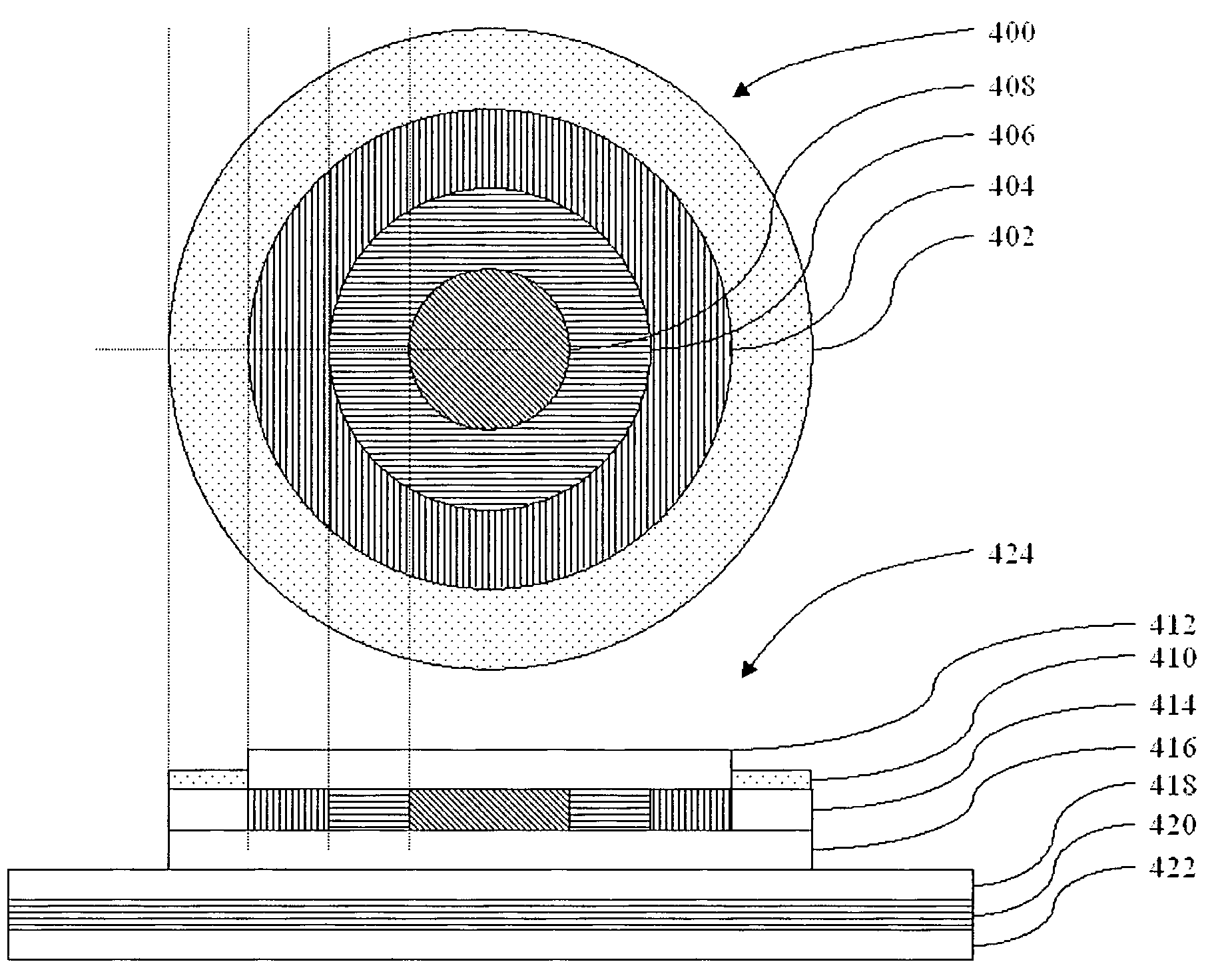
[0105]FIG. 4 illustrates the top-view 400 and cross sectional view 424 of a micro / nano-structured vertical cavity surface emitting laser. The electrical contact region 402 on the top-view and region 410 in the cross-sectional view surround the mode confinement region (MC-region) 404, Mode Shaping region (MS-region) 406 and the Light aperture region (LA-region) 408. The LA-region, MS-region and MC-region are also indicated by the hatched areas layers 414 of the cross-sectional view 424. However, the different thickness and the applied micro / nano-structuring is not indicated on this figure. Below layers 414 we have a partial semiconductor DBR top mirror or spacer layer 416. Above layers 414 the top mirror is completed by regrowth of a semiconductor DBR top mirror or dielectric top mirror 412. The FIG. 424 also shows the active layer 418, DBR bottom mirror layers 420 and the substrate 422.

[0106]The MS-region (region 406) has a long cavity resonance wavelength compared to the cavity res...


PUM


Abstract

This specification discloses a VCSEL (Vertical-Cavity Surface-Emitting Laser) device with single-mode output and optionally single polarization output. This device is given by lateral mode confinement by the PBG (Photonic Band-Gap) effect by shallow etching in a partial VCSEL top mirror. The PBG area encircles a MS-region (Mode-Shaping region), which is characterized by large longitudinal mode losses. The MS-region encircles the LA-region (Light Aperture region), which is characterised by low longitudinal mode losses. The MS-region does not contribute to the lateral mode-confinement to the LA-aperture, and the lateral modes confined by the PBG area. The VCSEL is thus optimized for single fundamental mode operation.

Description

FIELD OF THE INVENTION[0001]This invention pertains generally to the field of lateral mode-control in optical waveguides and particular to lateral mode-control in vertical-cavity surface-emitting lasers.BACKGROUND OF THE INVENTION[0002]Vertical-cavity surface-emitting lasers (VCSELs) have several advantages such as low-threshold, small size, on-wafer testability and high fiber coupling-efficiency. Single-mode VCSELs would be especially useful for applications such as data—(emission wavelength of λ=850 nm) and telecommunication (λ=1.3-1.7 μm), if sufficient high single-mode output powers (5-20 mW) could be extracted from a VCSEL.[0003]VCSELs emit radiation perpendicular to the semiconductor substrate plane, either from the top or the bottom of the device structure. A VCSEL is a surface-emitting laser having mirrors disposed parallel to the substrate surfaces that form and enclose an optical cavity between them. VCSELs usually have a substrate upon which a first mirror stack and secon...

Claims


Application Information

Patent Timeline
Patent Type & Authority Patents(United States)
IPC IPC(8): H01S5/00
CPCH01S5/183H01S5/105H01S5/18319H01S2301/166H01S5/18369H01S5/2224H01S5/18327H01S5/11
Inventor BIRKEDAL, DANBISCHOFF, SVENDJUHL, MICHAELMADSEN, MAGNUS HALDROMSTAD, FRANCIS PASCAL
Owner ALIGHT PHOTONICS
Why Eureka
Try Eureka