Gas turbine engine assembly and method of assembling same

a technology of gas turbine engines and assembly methods, which is applied in the direction of machines/engines, sustainable transportation, mechanical equipment, etc., can solve the problems of increasing the overall weight, the design complexity and/or manufacturing costs of such an engine, and the efficiency of the fan assembly

Active Publication Date: 2010-04-13
GENERAL ELECTRIC CO
View PDF11 Cites 251 Cited by
  • Summary
  • Abstract
  • Description
  • Claims
  • Application Information

AI Technical Summary

Problems solved by technology

However, utilizing a gearbox to reduce the speed of the fan assembly and thus increase the efficiency of the fan assembly reduces the quantity of airflow channeled to the booster compressor.
As a result, additional stages may be added to the booster compressor to achieve proper pressure, thus increasing the overall weight, design complexity and / or manufacturing costs of such an engine.

Method used


Image

  • Gas turbine engine assembly and method of assembling same
  • Gas turbine engine assembly and method of assembling same
  • Gas turbine engine assembly and method of assembling same

Examples


Embodiment Construction

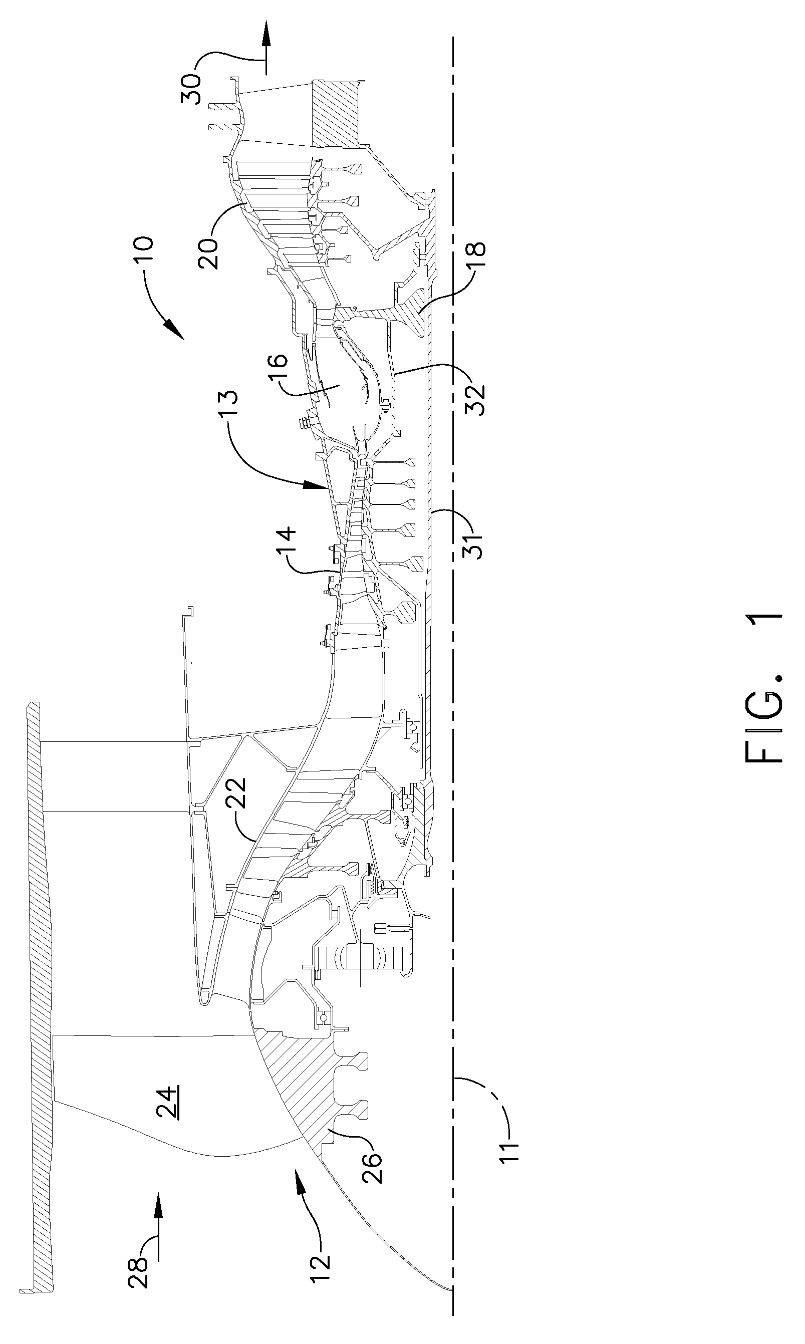
[0009]FIG. 1 is a schematic illustration of an exemplary gas turbine engine assembly 10 having a longitudinal axis 11. Gas turbine engine assembly 10 includes a fan assembly 12, and a core gas turbine engine 13 that includes a high-pressure compressor 14, a combustor 16, and a high-pressure turbine 18. In the exemplary embodiment, gas turbine engine assembly 10 also includes a low-pressure turbine 20 and a booster compressor 22.

[0010]Fan assembly 12 includes an array of fan blades 24 extending radially outward from a rotor disk 26. Engine 10 has an intake side 28 and an exhaust side 30. Booster 22 and low-pressure turbine 20 are coupled together by a first drive shaft 31, and compressor 14 and high-pressure turbine 18 are coupled together by a second drive shaft 32. Fan assembly 12 is supported on a novel frame 126 and driven by shaft 31 through reduction gearbox 100.

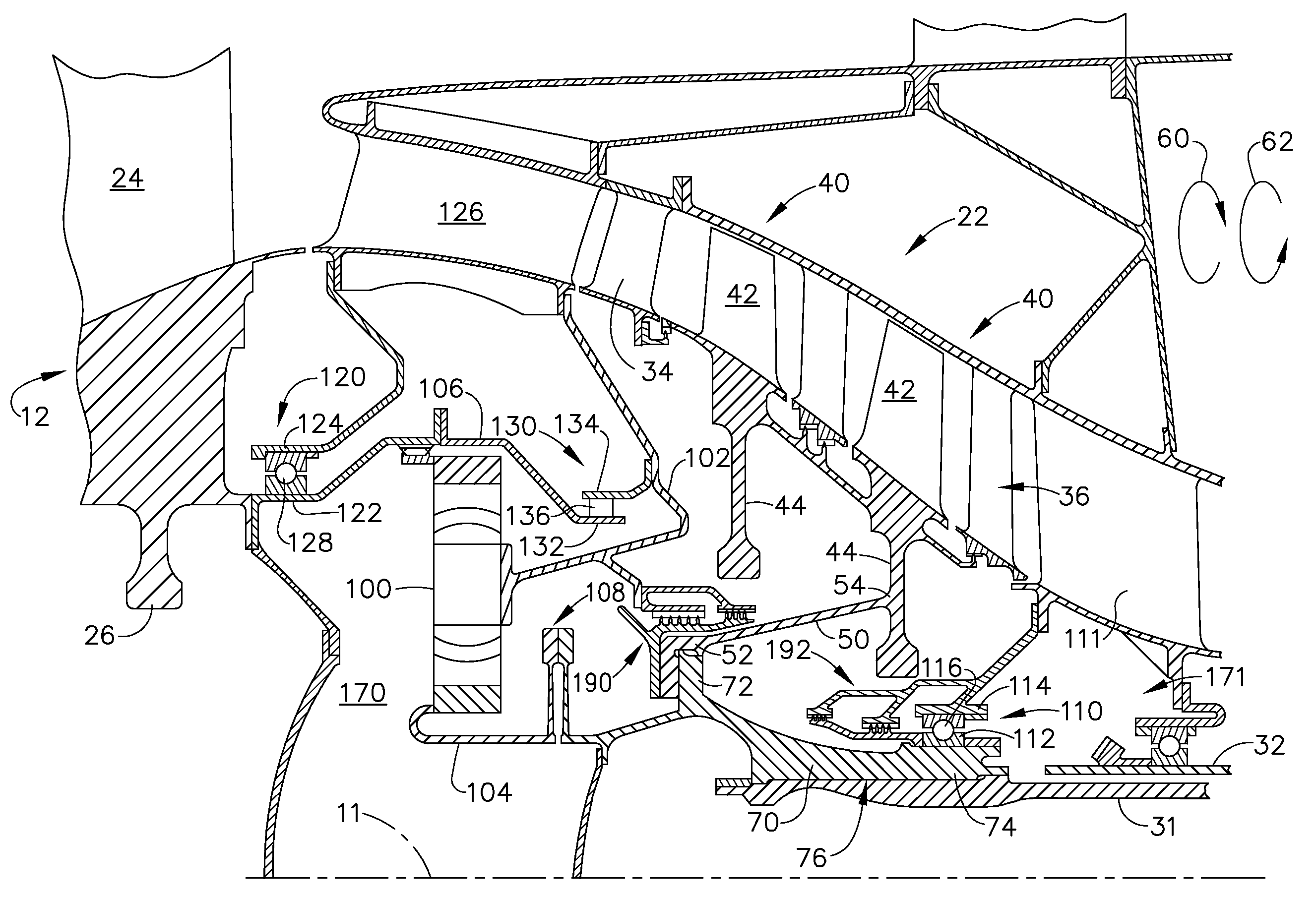
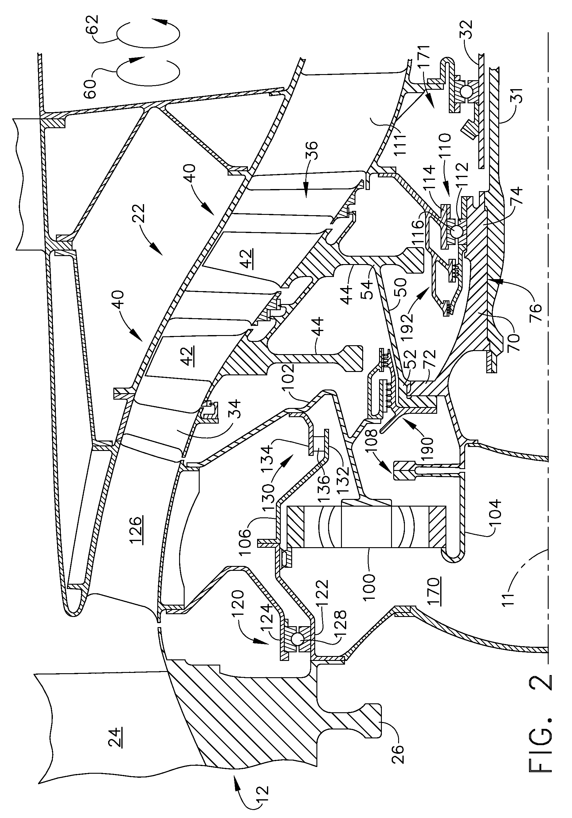
[0011]FIG. 2 is a schematic diagram of a portion of gas turbine engine assembly 10 shown in FIG. 1. As shown in FIG. ...


PUM


Abstract

A method of assembling a gas turbine assembly includes providing a core gas turbine engine including a high-pressure compressor, a combustor, and a turbine, coupling a low-pressure turbine axially aft from the core gas turbine engine, coupling a fan assembly axially forward from the core gas turbine engine, and coupling a booster compressor to the low-pressure turbine such that the booster compressor and the low-pressure turbine rotate at a first rotational speed.

Description

BACKGROUND OF THE INVENTION[0001]This invention relates generally to gas turbine engines, and more specifically to gas turbine engine assemblies and methods of assembling the same.[0002]At least some known gas turbine engines include a fan assembly, a core engine, and a low-pressure or power turbine. The core engine includes at least one compressor, a combustor, and a high-pressure turbine that are coupled together in a serial flow relationship. Air entering the core engine is mixed with fuel and ignited to form a high energy gas stream. The high energy gas stream flows through the high-pressure turbine to rotatably drive the high-pressure turbine and thus the compressor via a first drive shaft. The gas stream expands as it flows through the high-pressure turbine to facilitate driving the low-pressure turbine which rotatably drives the fan assembly through a second drive shaft.[0003]To improve engine efficiency, it is desirable to operate the fan assembly at a relatively low speed t...

Claims


Application Information

Patent Timeline
Patent Type & Authority Patents(United States)
IPC IPC(8): F02K3/02
CPCF02C7/36F02K3/06Y02T50/671F05D2230/60F05D2260/40311Y02T50/60
Inventor SCHILLING, JAN CHRISTOPHER
Owner GENERAL ELECTRIC CO
Why Eureka
Try Eureka