Heat exchanging wall, gas turbine using the same, and flying body with gas turbine engine

a technology of heat exchange wall and gas turbine, which is applied in the direction of positive displacement liquid engine, liquid fuel engine, lighting and heating apparatus, etc., can solve the problem of increasing the nox generated in the combustor, and achieve the effect of high heat exchange efficiency

Active Publication Date: 2010-04-13
MITSUBICHI HEAVY IND AERO ENGINES LTD +1
View PDF14 Cites 26 Cited by
  • Summary
  • Abstract
  • Description
  • Claims
  • Application Information

AI Technical Summary

Benefits of technology

[0010]It is an object of the present invention to provide a heat exchange wall which is high in heat exchange efficiency.
[0011]Another object of the present invention is to provide a heat exchange wall which is high in heat exchange efficiency and cheap.
[0012]Still another object of the present invention is to provide a heat exchange wall that can cool a combustor of a gas turbine at a high efficiency.
[0013]Still another object of the present invention is to provide a gas turbine in which an exhaust amount of NOx (Nitrogen Oxides) is low.

Problems solved by technology

Also, the temperature rise in the combustion gas leads to the increase in NOx generated in the combustor.

Method used


Image

  • Heat exchanging wall, gas turbine using the same, and flying body with gas turbine engine
  • Heat exchanging wall, gas turbine using the same, and flying body with gas turbine engine
  • Heat exchanging wall, gas turbine using the same, and flying body with gas turbine engine

Examples


first embodiment

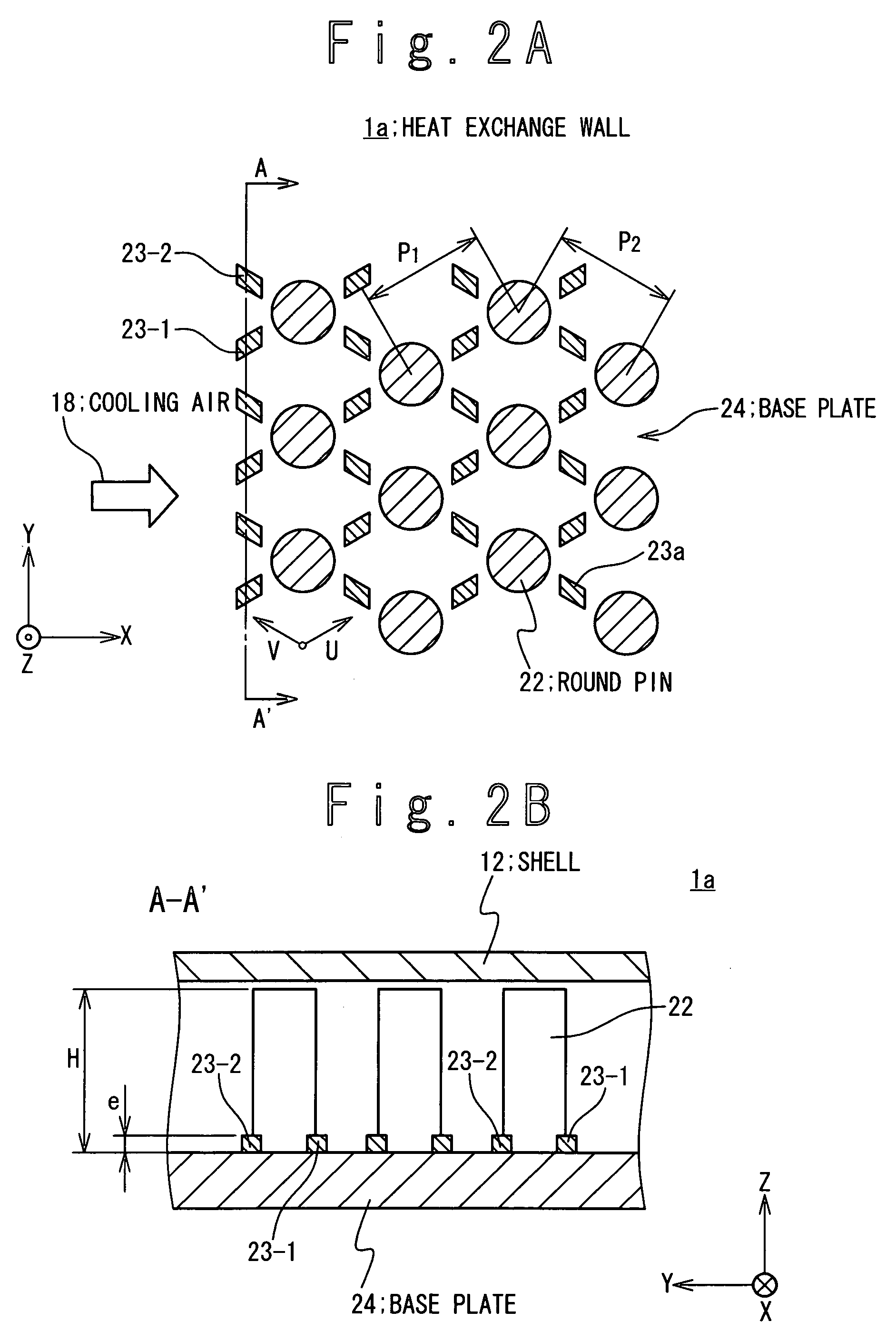
[0042]FIGS. 2A and 2B are a plan view and a cross sectional view showing a heat exchange wall 1a according to the present invention. The cooling air inlet 17 is provided on the upstream side of the heat exchange wall 1a in an X-axis direction. That is, cooling air 18 flows almost in the X-axis direction. A plurality of round pins or fin 22 are provided on a base plate 24 to extend into the Z-axis direction. The plurality of round pins 22 have a same cylindrical shape. The plurality of round pins 22 are periodically arranged in a pitch P1 in the direction of a first coordinate axis U parallel to the base plate 24, and are periodically arranged in a pitch P2 in the direction of a second coordinate axis V parallel to the base plate 24, and intersecting with the first coordinate axis U. It is desirable that the heat exchange wall 1a is mounted to the shell 12 such that a bisector of the first coordinate axis U and the second coordinate axis V is orthogonal to an average direction of the...

second embodiment

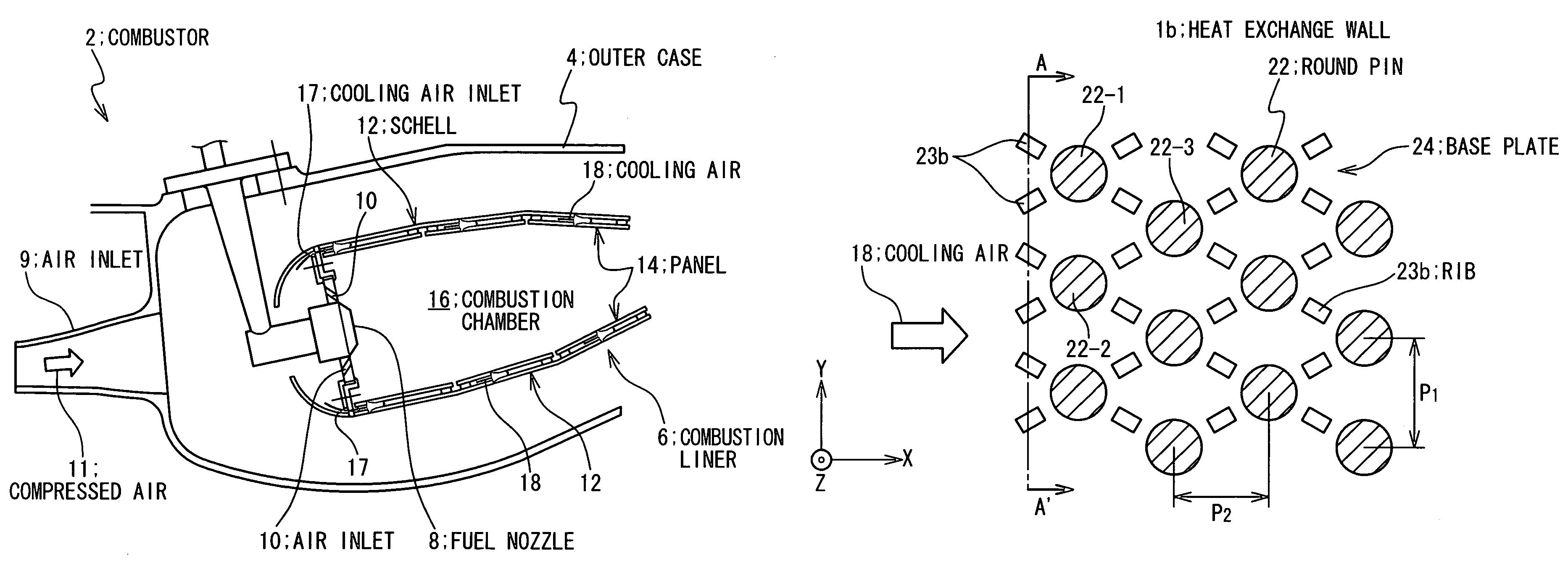
[0053]In the second embodiment, the pins 22 are periodically arranged in a pitch P1 in the Y-axis direction, and lines of the pins 22 are arranged in a pitch P2 periodically in the X-axis direction. It is supposed that the two of the pins 22 adjacent in the Y-axis direction in one line are a pin 22-1 and a pin 22-2. In this case, one 22-3 of the pins 22 in one line adjacent to the line containing the pin 22-1 and the pin 22-2 is arranged on an intermediate position in the Y-axis direction between the pin 22-1 and the pin 22-2. That is, the line containing the pin 22-3 is parallel to the line containing the pins 22-1 and 22-2 in the Y-axis direction and is shifted from the line containing the pins 22-1 and 22-2 by a half pitch P1 / 2 in the Y-axis direction.

[0054]The pin 22 exhibits the further effective cooling performance, under the heat transfer condition that the Biot number (=((Heat Transfer Coefficient*Representative Length) / Thermal Conductivity), where the representative length ...

third embodiment

[0071]Next, FIGS. 7A and 7B are plan view and a cross sectional view showing the structure of the heat exchange wall 1c according to the present invention. Referring to FIG. 7A, the cooling air is supplied to the heat exchange wall 1c in the X-axis direction.

[0072]The plurality of pins 22 are provided on the base plate 24. The plurality of pins 22 have the same cylindrical shape as in the first embodiment and connected with the surface of the base plate 24. A plurality of pins 26 as ribs are further provided on the base plate 24. The plurality of pins 26 may have the same cylindrical shape as that of the plurality of pins 22. The pins 22 and the pins 26 are alternately arranged in the pitch P1 in the Y-axis direction. It is supposed that the pins 22 and the pins 26 adjacent in the Y-axis direction are pins 22-1 and 22-2 and pins 26-1 and 26-2. At this time, the line containing the pin 22-2 and the pin 26-2 is adjacent to the line containing the pin 22-1 and the pin 26-1 apart from t...


PUM


Abstract

A heat exchange wall include a base plate; a plurality of first protrusions distributedly provided on a surface of the base plate, and a plurality of second protrusions distributedly provided on the base plate surface. The height of the second protrusion in a normal direction of the base plate is desirably less than ½ of a height of the first protrusion in the normal direction. The height of the second protrusion in the normal direction is desirably between 1 / 20 and ¼ of the height of the first protrusion in the normal direction. More desirably, the height of the second protrusion in the normal direction is 1 / 10 of the height of the first protrusion in the normal direction.

Description

BACKGROUND OF THE INVENTION[0001]1. Field of the Invention[0002]The present invention relates to a structure of a heat exchange wall, and more particularly relates to a structure of a heat exchange wall which is suitable for cooling a combustor of a gas turbine, and a flying body with a gas turbine engine in which provided with the heat exchange wall.[0003]2. Description of the Related Art[0004]A gas turbine contains a compressor for compressing air, a combustor for combusting fuel using the air compressed by the compressor and generating combustion gas of a high temperature, and a turbine for obtaining a driving force through the expansion of the combustion gas from the combustor. In order to improve a thermal efficiency of the gas turbine, a combustor has been developed for combusting the fuel at a higher temperature. Also, the temperature rise in the combustion gas leads to the increase in NOx generated in the combustor. In order to decrease the load on the environment exerted by...

Claims


Application Information

Patent Timeline
Patent Type & Authority Patents(United States)
IPC IPC(8): F02C1/00F02G3/00F23R3/00
CPCF23R3/002F23R3/005Y02T50/675F28F3/02F28F3/022F28F13/12F23R2900/03043Y02T50/60
Inventor NAKAE, TOMOYOSHITAKEISHI, KENICHIROMATSUURA, MASAAKIKITAMURA, TSUYOSHIMORIWAKI, ATSUSHI
Owner MITSUBICHI HEAVY IND AERO ENGINES LTD
Why Eureka
Try Eureka