
Method and apparatus for automatically disarming a security system

a security system and automatic disassembly technology, applied in the field of security systems, can solve the problems of security risks, large number of false alarms, and slow response time during a true event or emergency

Active Publication Date: 2010-04-13
JOHNSON CONTROLS TYCO IP HLDG LLP
View PDF12 Cites 96 Cited by
  • Summary
  • Abstract
  • Description
  • Claims
  • Application Information

AI Technical Summary

Benefits of technology

The patent describes a security system that can be remotely controlled to arm or disarm the system. It uses RF technology to detect the presence of a disarm device near a door and sends a signal to a control panel to disarm the system. The system can also be set to a disarmed mode based on motion or the detection of a disarm device packet. The technical effect of this invention is to provide a more efficient and effective security system that can be easily controlled and set to different modes based on the needs of the system.

Problems solved by technology

Unfortunately, a large number of false alarms are generated due to human error.
Also, a great number of false alarms may result in slower response time during a true event or emergency due to less available security personnel or a perceived lack of urgency.
Setting the system to disarm based on simply unlocking a door also causes security risks, as locks can be picked or potentially unlocked by breaking a window or door panel, then unlocking the door from the inside.
False alarms are also often generated when people are within the perimeter and have armed the sensors along the perimeter.

Method used


Image

  • Method and apparatus for automatically disarming a security system
  • Method and apparatus for automatically disarming a security system
  • Method and apparatus for automatically disarming a security system

Examples


Embodiment Construction

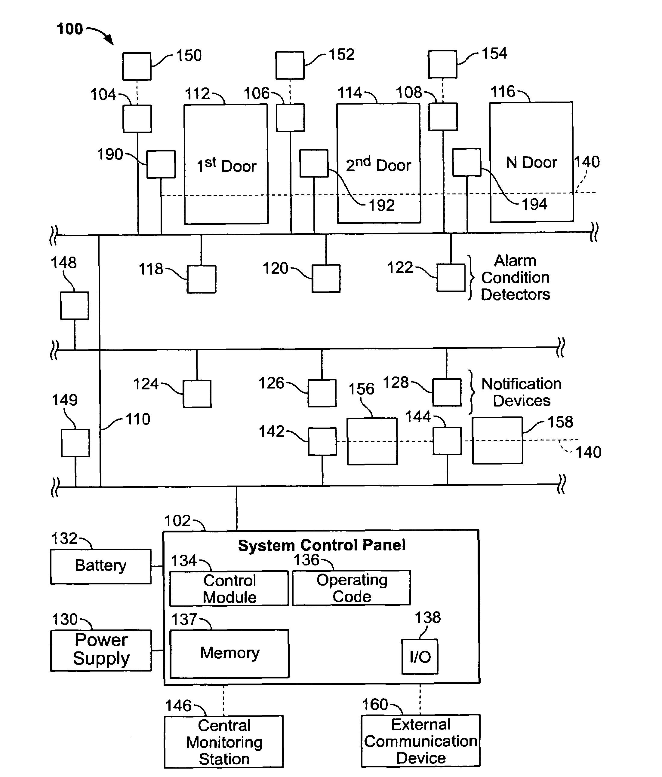
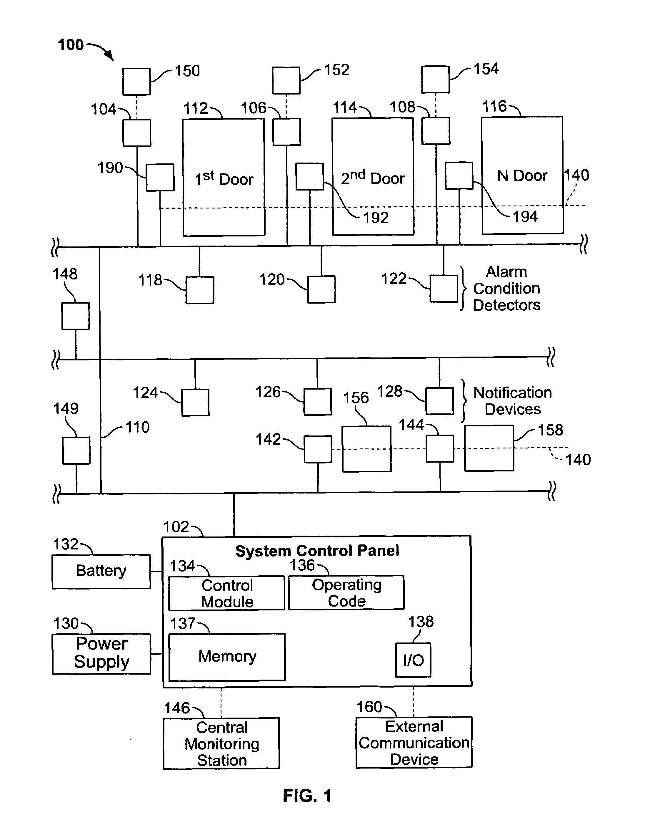
[0015]FIG. 1 illustrates a security system 100 which has a system control panel 102 for monitoring and / or controlling devices installed on a network 110. The devices may detect and / or control door openings and closings, detect motion, detect alarm conditions, notify people within an area about alarm conditions, or accomplish other functions which may be desired. For example, the system 100 may be used within a light industrial building or a residence.

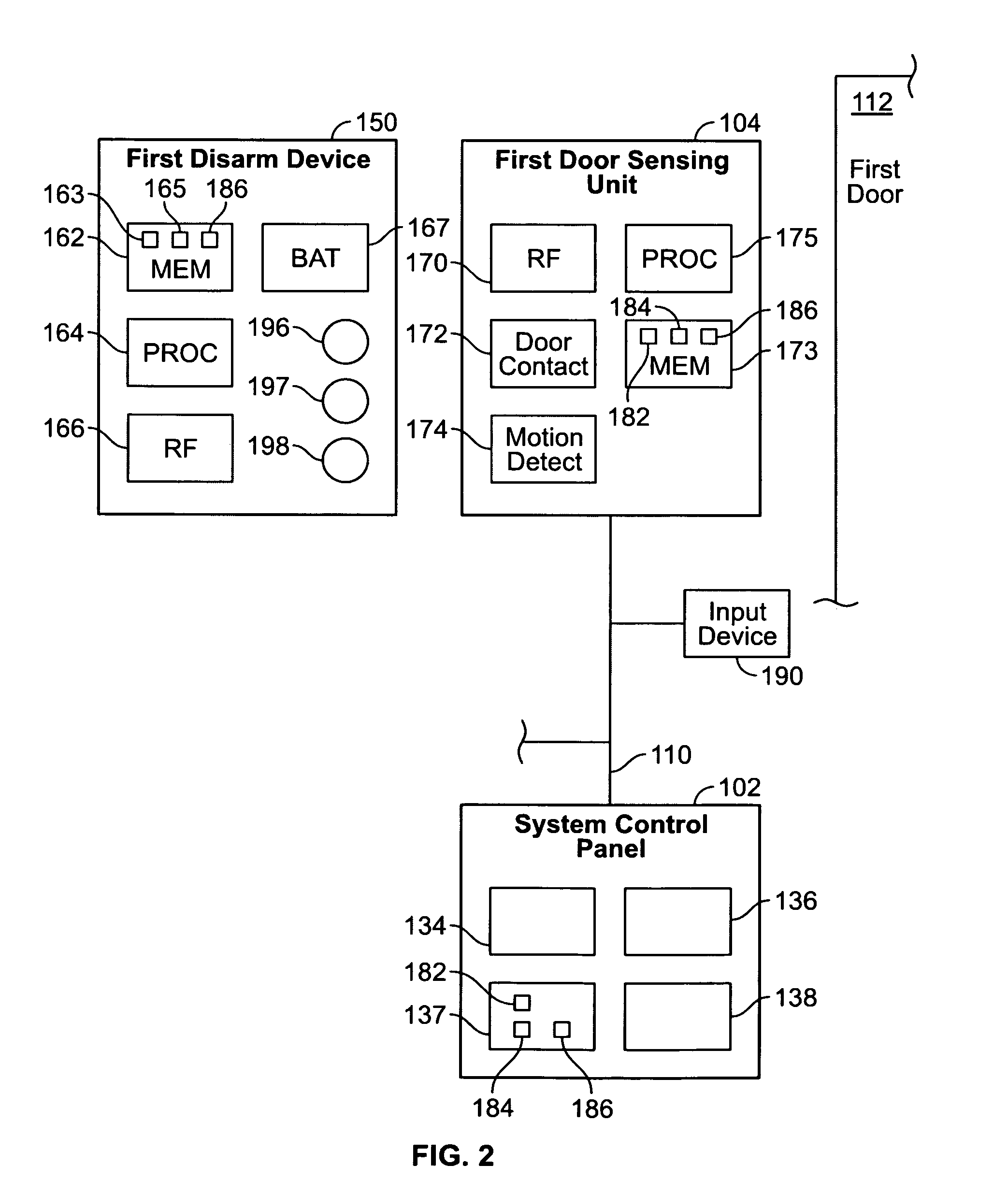
[0016]The system 100 has one or more door sensing units, such as first door sensing unit 104, second door sensing unit 106 through N door sensing unit 108 which may be configured to monitor first door 112, second door 114, through N door 116, respectively. Each of the first through N sensing units 104-108 may receive signals from and send signals to, any of first, second through N disarm devices 150, 152 and 154. By way of example only, the signals may be electrical signals, packets, and the like. The first through N sensing units 104-1...


PUM


Abstract

A security system comprises a system control panel for arming and disarming the security system. A door sensing unit comprises a first radio frequency (RF) transceiver interconnected with the system control panel over a network. The first RF transceiver is mounted proximate to a door that defines at least a portion of a perimeter around an area to be monitored by the security system. The first RF transceiver has an RF detection field proximate to the door. A disarm device comprises a second RF transceiver that automatically transmits a disarm device packet. The first RF transceiver receives the disarm device packet when the second RF transceiver is within the RF detection field. The first RF transceiver sends a disarm message to the system control panel over the network to disarm the security system based on at least the disarm device packet.

Description

BACKGROUND OF THE INVENTION[0001]This invention relates generally to security systems, and more particularly, to automatically disarming a security system to prevent false alarms.[0002]Security systems are installed in homes and businesses to protect the premises within a perimeter. Unfortunately, a large number of false alarms are generated due to human error. The home or business owner is typically responsible for costs incurred by police or other security personnel who are sent to respond to a false alarm. Also, a great number of false alarms may result in slower response time during a true event or emergency due to less available security personnel or a perceived lack of urgency.[0003]When the security system is armed, the person entering the home or business has to disable the alarm by, for example, entering a code into a panel or input device such as a keypad, or finding and holding a radio frequency identification (RFID) tag up to an RFID reader within a set amount of time. I...

Claims


Application Information

Patent Timeline
Patent Type & Authority Patents(United States)
IPC IPC(8): G08B13/08
CPCG08B25/14G08B25/008G08B13/08
Inventor SHARMA, RAMAN KUMARPARENTEAU, ROGERMUNOZ, JUAN FRANCISCO BOGARIN
Owner JOHNSON CONTROLS TYCO IP HLDG LLP
Learn More