Camera surveillance system and method for displaying multiple zoom levels of an image on different portions of a display

a camera and zoom level technology, applied in the field of surveillance cameras, can solve the problems of increasing system costs, affecting the operation of the camera, and the time required for obtaining the image becomes longer, so as to improve the operability, facilitate the control of the camera and the effect of directing the camera

Inactive Publication Date: 2010-04-13
SONY CORP
View PDF37 Cites 16 Cited by
  • Summary
  • Abstract
  • Description
  • Claims
  • Application Information

AI Technical Summary

Benefits of technology

[0011]Accordingly, it is an object of the present invention to provide a monitoring system and method, program, and recording medium, capable of allowing confirmation of an image of the photography range beforehand, capable of notifying the user at a glance regarding the relation between the range over which images can be taken in and the photography range, and capable of continuously monitoring portions to be monitored in particular.
[0017]The monitoring system according to the present invention thus has first and second camera units capable of moving the photography direction thereof over a wide range, and the second camera unit can be operated (controlled), using a first group image display portion where multiple sets of image data taken with the first camera unit are gathered with positional information of the first camera unit assembled therein as a GUI. In other words, controlling the second camera unit based on the positional information of the first camera unit allows particular positions regard which monitoring is desired to be continuously taken, recorded, and / or displayed. Further, the movement range image in the maximum range over which the image-taking unit can be moved is displayed, so the direction of image-taking to obtain images of a desired range can be readily set, thereby improving operability.
[0018]According to the present invention configured thus, what sort of image is going to be acquired from the movement range of a pan / tilter device for a camera having a wide movement range can easily be displayed as user information, and camera control can be easily carried out using the display. Even in the event that there is a need to monitor a wide-range area, the camera can be directed easily, and necessary images can be acquired without mistakes.
[0020]Thus, the present image enables the range over which photography can be made in the spatial direction to be expanded, the image-taking intervals in the time direction can be made shorter, and further, resolution can be improved. Particularly, specified areas can be taken as moving image data, and recorded and / or displayed.

Problems solved by technology

This has resulted in increased costs of the system.
The wider the range of photography is, the greater the number of still images making up the wide-range still image, meaning that the time required for obtaining the image becomes longer, resulting in the problem of longer cycles for obtaining a linked image.
However, the area regarding which monitoring is desired is actually often much more restricted.
Also, there was no way therein to notify the user at a glance regarding the relation between the range over which images can be taken in and the photography range.
Moreover, even areas to be monitored in further detail are taken as multiple images, so a certain amount of time is required to photograph those portions again, and accordingly, such portions cannot be monitored at time spans shorter than the certain amount of time.

Method used


Image

  • Camera surveillance system and method for displaying multiple zoom levels of an image on different portions of a display
  • Camera surveillance system and method for displaying multiple zoom levels of an image on different portions of a display
  • Camera surveillance system and method for displaying multiple zoom levels of an image on different portions of a display

Examples


Embodiment Construction

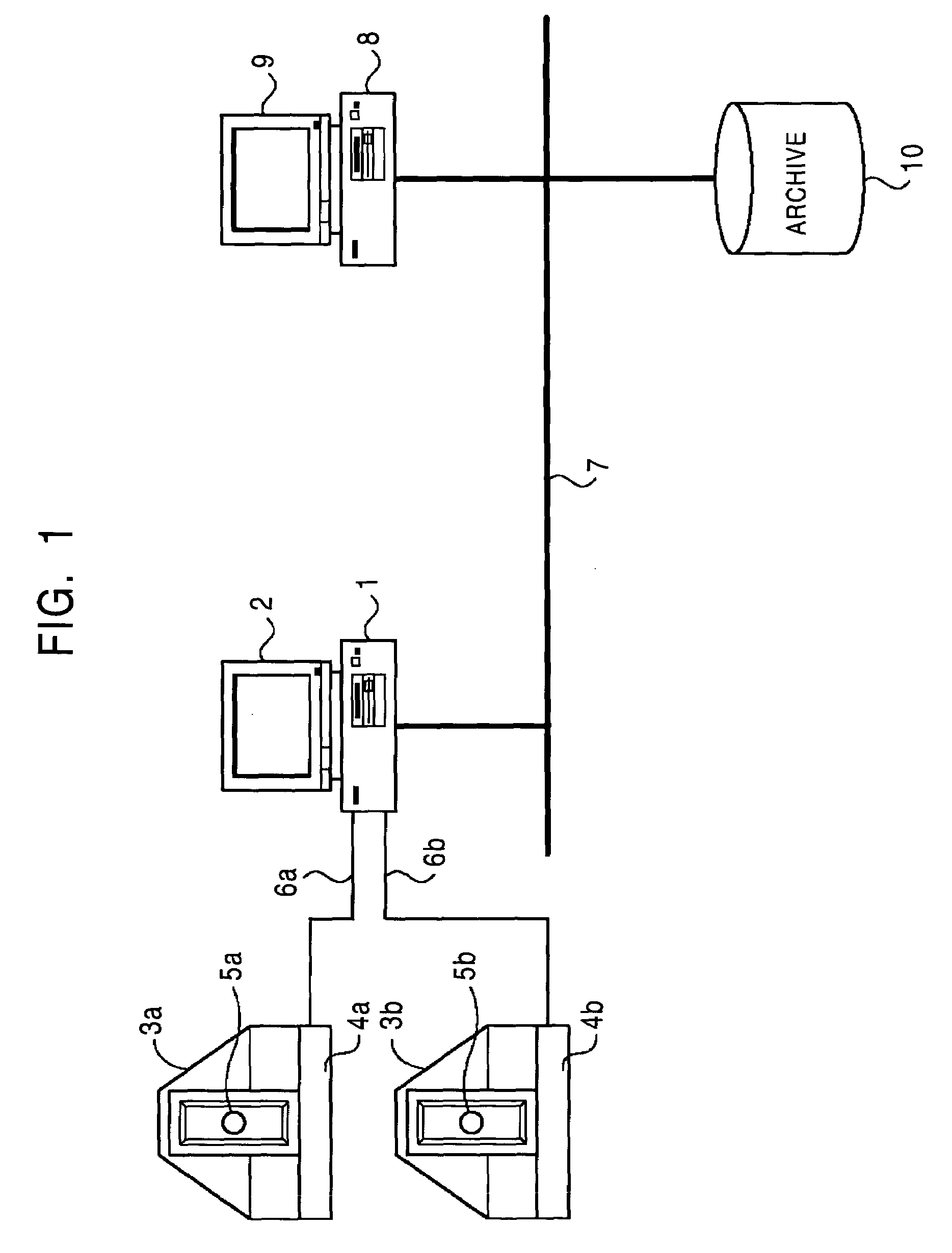
[0032]The following is a description of an embodiment of the present invention, with reference to the drawings. FIG. 1 illustrates a schematic configuration of an embodiment of the present invention. A computer 1 connected to a display 2 controls camera units 3a and 3b. The example shown in FIG. 1 is an example of a system wherein one computer 1 controls two camera units 3a and 3b. Other arrangements may be made wherein one computer controls a greater number of cameras.

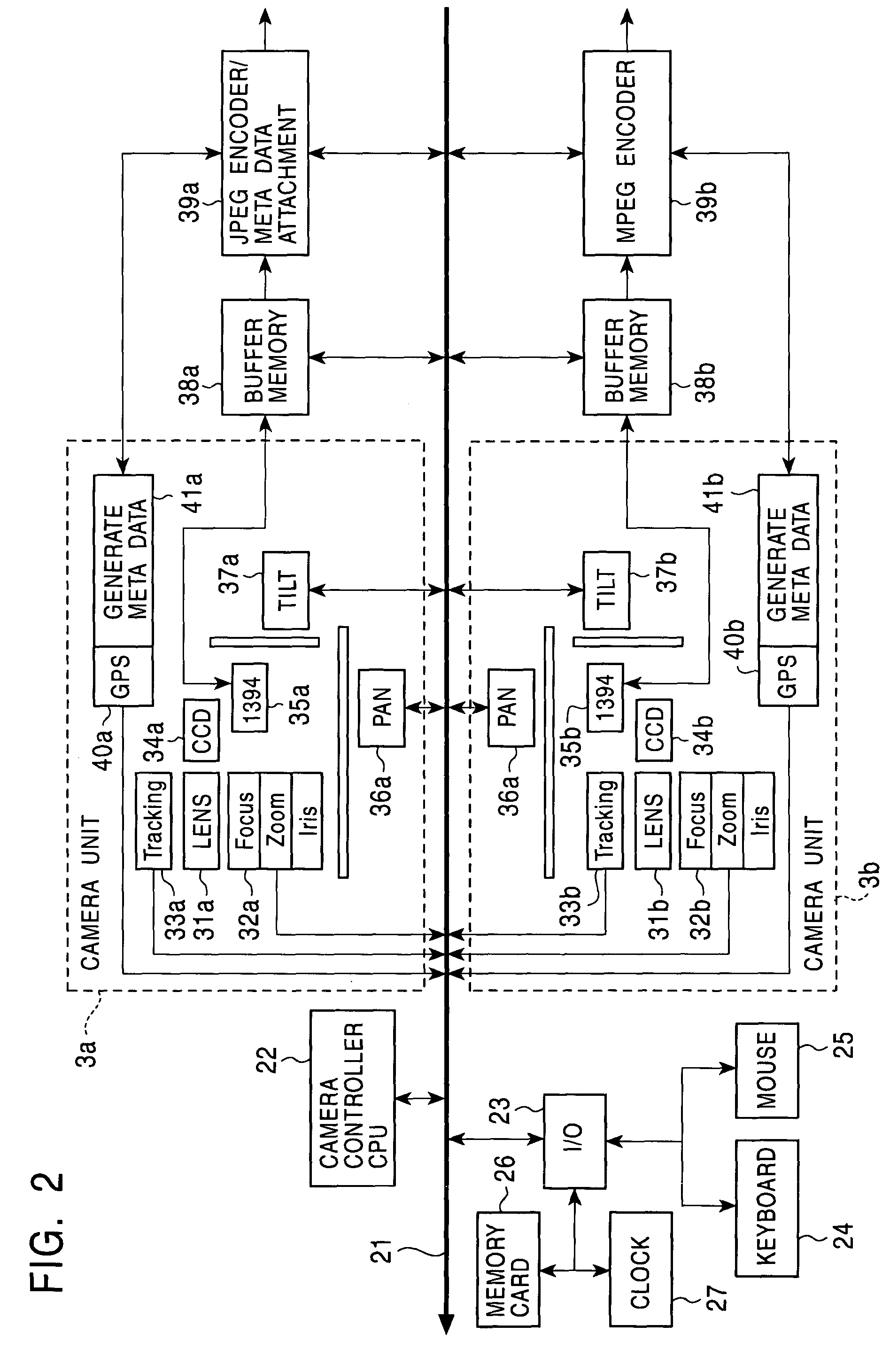
[0033]The camera units 3a and 3b have pan / tilt units 4a and 4b, and cameras 5a and 5b configured integrally. The camera units 3a and 3b are installed so as to be capable of taking images of distant areas to be monitored. As an example, the cameras 5a and 5b have telephoto lenses with magnification of 10 times, 70 times, or the like, and can take images anywhere from ten meters or so up to several kilometers away. With this embodiment, the camera unit 3b configured of the pan / tilt unit 4b and the camera unit 5b is for ...


PUM


Abstract

Positional and elevation data obtained from a camera unit is correlated with coordinates in an entire image display portion, used as a GUI having positional information to select a specified image with a mouse. Which frame this corresponds to in the entire image is calculated, and further, the position within the clicked frame is calculated. The calculated positional information is converted into positional information and elevation data of the frame. The camera unit is controlled with the positional information and elevation data from the camera unit, and an image of a range indicated by a specified image display frame superimposed on the display portion is taken, and stored and / or displayed. This allows confirmation an image of a range to be photographed beforehand, and the user can tell the relation between the range capable of acquiring images and the photography range at a glance, so desired portions can be continuously monitored.

Description

BACKGROUND OF THE INVENTION[0001]1. Field of the Invention[0002]The present invention relates to a monitoring system and method, program, and recording medium, applied to surveillance cameras and the like.[0003]2. Description of the Related Art[0004]Conventionally, monitoring systems have been used to monitor situations over wide ranges. Examples of monitoring systems are used to monitor marine and river areas, off-limit areas, observation of animal behaviors, and so forth. Such monitoring systems take images over a wide range, and accordingly video cameras with an extremely great number of pixels have been used. This has resulted in increased costs of the system.[0005]An alternative arrangement has been proposed, wherein the photography range of the camera is shifted in order while taking still images, and a great number of still images are linked so as to generate an image of a range to be monitored. In this case, the linked image generated by linking a great number of still image...

Claims


Application Information

Patent Timeline
Patent Type & Authority Patents(United States)
IPC IPC(8): H04N7/18H04N7/12
CPCH04N5/23216H04N7/185H04N7/181H04N23/62
Inventor HASEGAWA, HIROYUKIHAMA, HIDEKINEDU, HIROSHIKUROYA, TAKEYOSHIKUREBAYASHI, MASAAKI
Owner SONY CORP
Why Eureka
Try Eureka