Industrial truck

a technology for industrial trucks and trucks, applied in the field of working machines, to achieve the effect of good metering capability of service brakes and little complexity

Inactive Publication Date: 2010-04-20
LINDE MATERIAL HANDLING
View PDF10 Cites 3 Cited by
  • Summary
  • Abstract
  • Description
  • Claims
  • Application Information

AI Technical Summary

Benefits of technology

[0009]This object is achieved according to the invention by providing a brake valve that is operatively connected to a service brake input device, such as a brake pedal. The brake valve can be acted upon in the direction of a reduction in the brake-release pressure arising at the spring-loaded brake when the service brake input device is actuated. It being possible, on actuation, for the service brake input device to be operatively connected to a pre-stressed spring device, which is operatively connected to the brake valve and can be acted upon in the direction of an increase in the spring force on increasing actuation of the service brake input device. By means of a brake valve, which produces the brake-release pressure for acting on the spring-loaded brake so as to bring it into the release position, and which can be acted upon in the direction of a reduction in the brake-release pressure by means of a service brake input device, the spring-loaded brake can be acted upon in a controlled manner in the direction of the braking position, and the spring-loaded brake can be used as the service brake with little complexity in terms of design. With a pre-stressed spring device, which acts upon the brake valve in the direction of a reduction in the brake-release pressure when the service brake input device is actuated, good metering capability of the service brake is achieved. In contrast to a spring device that is operatively connected to the brake valve and has a linear characteristic, in the case of which the brake-release pressure is reduced linearly and proportionally with respect to the actuation of the service brake input device, which results in a long idle travel of the service brake input device up to the beginning of the braking function of the spring-loaded brake used as the service brake owing to a braking torque being built up by the spring-loaded brake and, thus, results in merely a short actuation travel of the service brake input device being available in which a metering capability of the spring-loaded brake used as the service brake is made possible by means of the brake-release pressure being controlled, with a pre-stressed spring device that is operatively connected to the brake valve and acts upon the brake valve in the direction of a reduction in the brake-release pressure, a short idle travel of the service brake input device can be achieved up to the point at which a braking torque of the spring-loaded brake is built up and a long actuation travel of the service brake input device can be made available, in which the brake-release pressure of the spring-loaded brake used as the service brake can be reduced in a controlled manner and, thus, metered braking of the working machine can be achieved.

Problems solved by technology

In contrast to a spring device that is operatively connected to the brake valve and has a linear characteristic, in the case of which the brake-release pressure is reduced linearly and proportionally with respect to the actuation of the service brake input device, which results in a long idle travel of the service brake input device up to the beginning of the braking function of the spring-loaded brake used as the service brake owing to a braking torque being built up by the spring-loaded brake and, thus, results in merely a short actuation travel of the service brake input device being available in which a metering capability of the spring-loaded brake used as the service brake is made possible by means of the brake-release pressure being controlled, with a pre-stressed spring device that is operatively connected to the brake valve and acts upon the brake valve in the direction of a reduction in the brake-release pressure, a short idle travel of the service brake input device can be achieved up to the point at which a braking torque of the spring-loaded brake is built up and a long actuation travel of the service brake input device can be made available, in which the brake-release pressure of the spring-loaded brake used as the service brake can be reduced in a controlled manner and, thus, metered braking of the working machine can be achieved.

Method used


Image

  • Industrial truck
  • Industrial truck
  • Industrial truck

Examples


Embodiment Construction

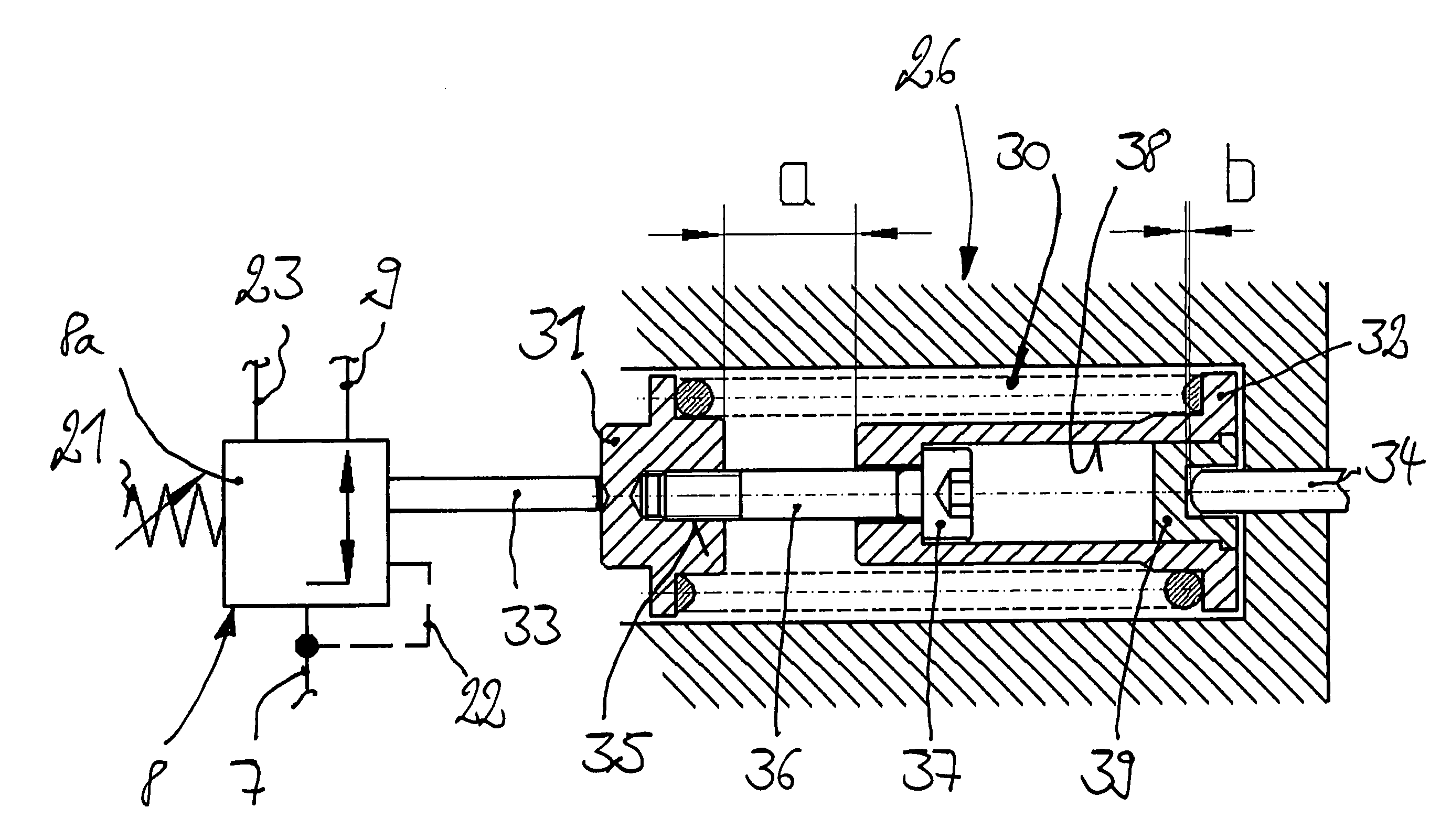
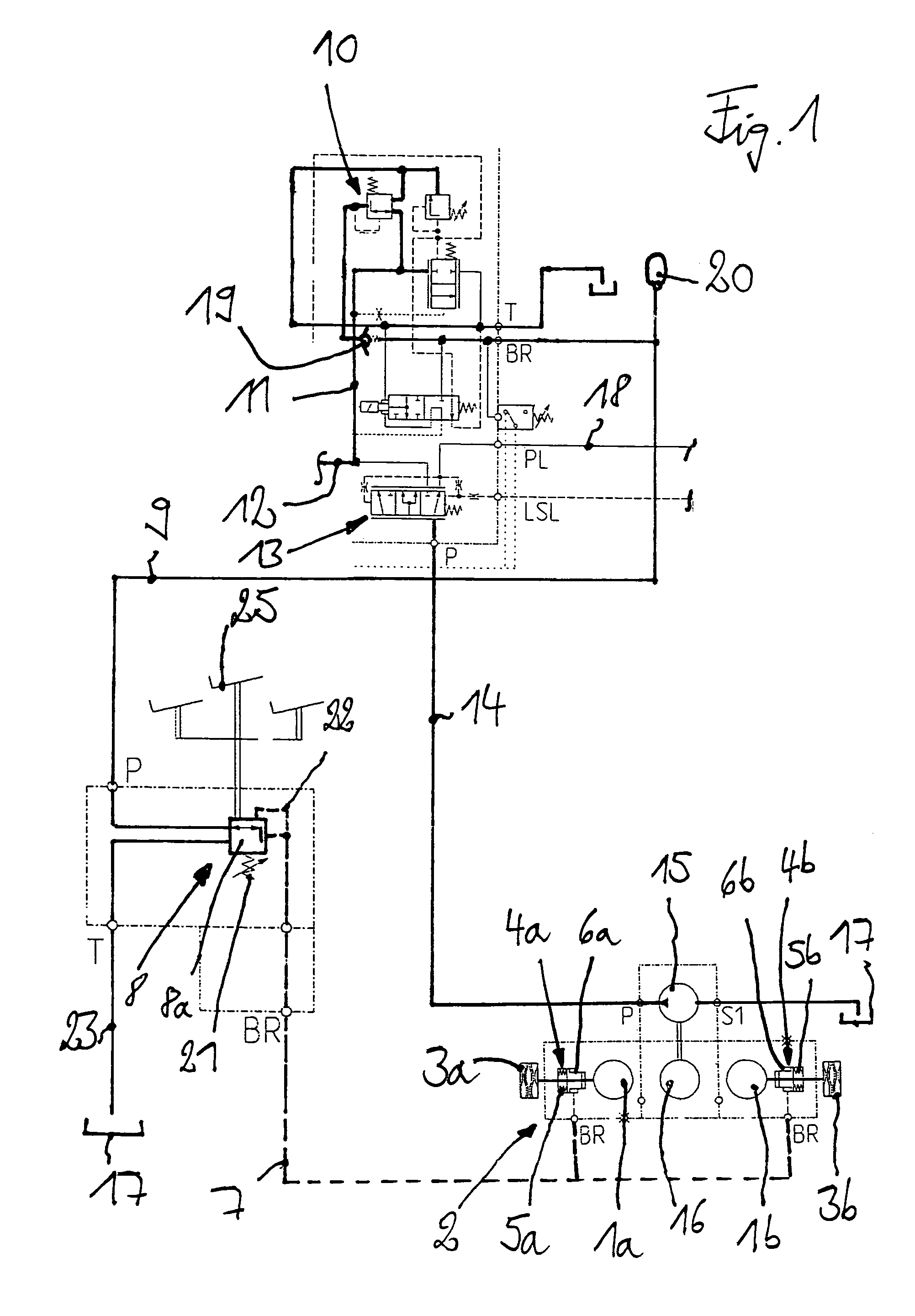
[0034]FIG. 1 illustrates a hydraulic circuit diagram of a working machine in the form of an industrial truck. The industrial truck has a traction drive, which is formed by traction motors 1a, 1b, for example hydraulic motors or electric motors, which are operatively connected to drive wheels (not illustrated) via a spring-loaded brake 2. The spring-loaded brake 2 comprises, for example, brake devices 3a, 3b, which are in the form of multiple-disc brakes associated with the traction motors 1a, 1b, and can be acted upon by means of an actuating device 4a, 4b so as to be moved between a release position and a braking position. The actuating device 4a, 4b comprises an actuating piston, which can be acted upon by a spring 5a, 5b in the direction of the braking position of the brake devices 3a, 3b. A control pressure space 6a, 6b, which acts in the direction of the release position of the brake devices 3a, 3b and, thus, counter to the spring 5a, 5b, and is connected to a brake-release lin...


PUM


Abstract

A working machine, such as an industrial truck, having a spring-loaded brake having a braking position and a release position and controlled by a brake valve producing a brake-release pressure. The brake valve is operatively connected to a service brake input device, such as a brake pedal, and can be acted upon in the direction of a reduction in the brake-release pressure arising at the spring-loaded brake when the service brake input device is actuated. It being possible, on actuation, for the service brake input device to be operatively connected to a pre-stressed spring device, which is operatively connected to the brake valve and can be acted upon in the direction of an increase in the spring force on increasing actuation of the service brake input device.

Description

CROSS-REFERENCE TO RELATED APPLICATION[0001]This application claims priority to German Application No. 10 2005 022 554.3, filed May 17, 2005, and German Application No. 10 2006 019 088.2, filed Apr. 25, 2006, both of which applications are herein incorporated by reference in their entirety.BACKGROUND OF THE INVENTION[0002]1. Field of the Invention[0003]The invention relates to a working machine, such as an industrial truck, having a spring-loaded brake. The brake has a braking position and a release position, and can be controlled by means of a brake valve producing a brake-release pressure.[0004]2. Technical Considerations[0005]In the case of mobile working machines in the form of industrial trucks, a spring-loaded brake is provided, which is used as a parking brake. Using the spring-loaded brake, which is acted upon in the braking position, the industrial truck can be kept at a standstill on slopes or in the case of a traction drive which is not being driven. During driving of the...

Claims


Application Information

Patent Timeline
Patent Type & Authority Patents(United States)
IPC IPC(8): B60T7/12
CPCB66F9/07509B60T13/22B60T7/04B60T15/041B66F9/075
Inventor DOLGER, MARCUSHUBER, FRANZHOLSCHER, ANDREASWELSCHOF, BERNWARD
Owner LINDE MATERIAL HANDLING
Why Eureka
Try Eureka