System and method for tracking eyeball motion

a technology of eyeball motion and system, applied in the field of eyeball motion tracking system, can solve the problems of affecting the accuracy of eyeball motion tracking, and introducing errors into the range and/or range rate measurement, so as to reduce invasiveness to the individual, increase speed, and no latency

Active Publication Date: 2010-04-20
AEVA INC
View PDF70 Cites 24 Cited by
  • Summary
  • Abstract
  • Description
  • Claims
  • Application Information

AI Technical Summary

Benefits of technology

[0006]One aspect of the invention relates to detecting position information related to a face, and more particularly to an eyeball in a face, using a detection and ranging system, such as a Radio Detection And Ranging (“RADAR”) system, or a Light Detection And Ranging (“LIDAR”) system. The position information may include a location of the eyeball, translational motion information related to the eyeball (e.g., displacement, velocity, acceleration, jerk, etc.), rotational motion information related to the eyeball (e.g., rotational displacement, rotational velocity, rotational acceleration, etc.) as the eyeball rotates within its socket. One of the advantages of the implementation of a detection and ranging system in detecting position information related to the eyeball may include an increased speed at which the position information may be determined. In fact, in some implementations, the determination of the position information may be substantially instantaneous with substantially no latency. Another advantage of the implementation of a detection and ranging system in detecting position information related to the eyeball may include enabling eyeball motion to be determined from an increased distance and / or with a reduced invasiveness to the individual.

Problems solved by technology

However, conventional eyeball motion tracking systems, such as stereo systems, may not provide position information related to an eyeball with enough speed and / or accuracy for all of the possible applications of eyeball motion tracking.
In general, these systems may also be hampered by an inability to determine position information related to an eyeball from a relatively extended distance.
These and other drawbacks associated with conventional eyeball motion tracking systems and methods exist.
Since different parts of the mirror are moving at different velocities, different parts of the target beam experience different Doppler shifts, which may introduce errors into the range and or range rate measurements.
For example, radiation output from the optical cavity to a device may constitute a loss.
Other losses may also be present, such as losses due to imperfections in the optical elements, or other parasitic losses.

Method used


Image

  • System and method for tracking eyeball motion
  • System and method for tracking eyeball motion
  • System and method for tracking eyeball motion

Examples


Embodiment Construction

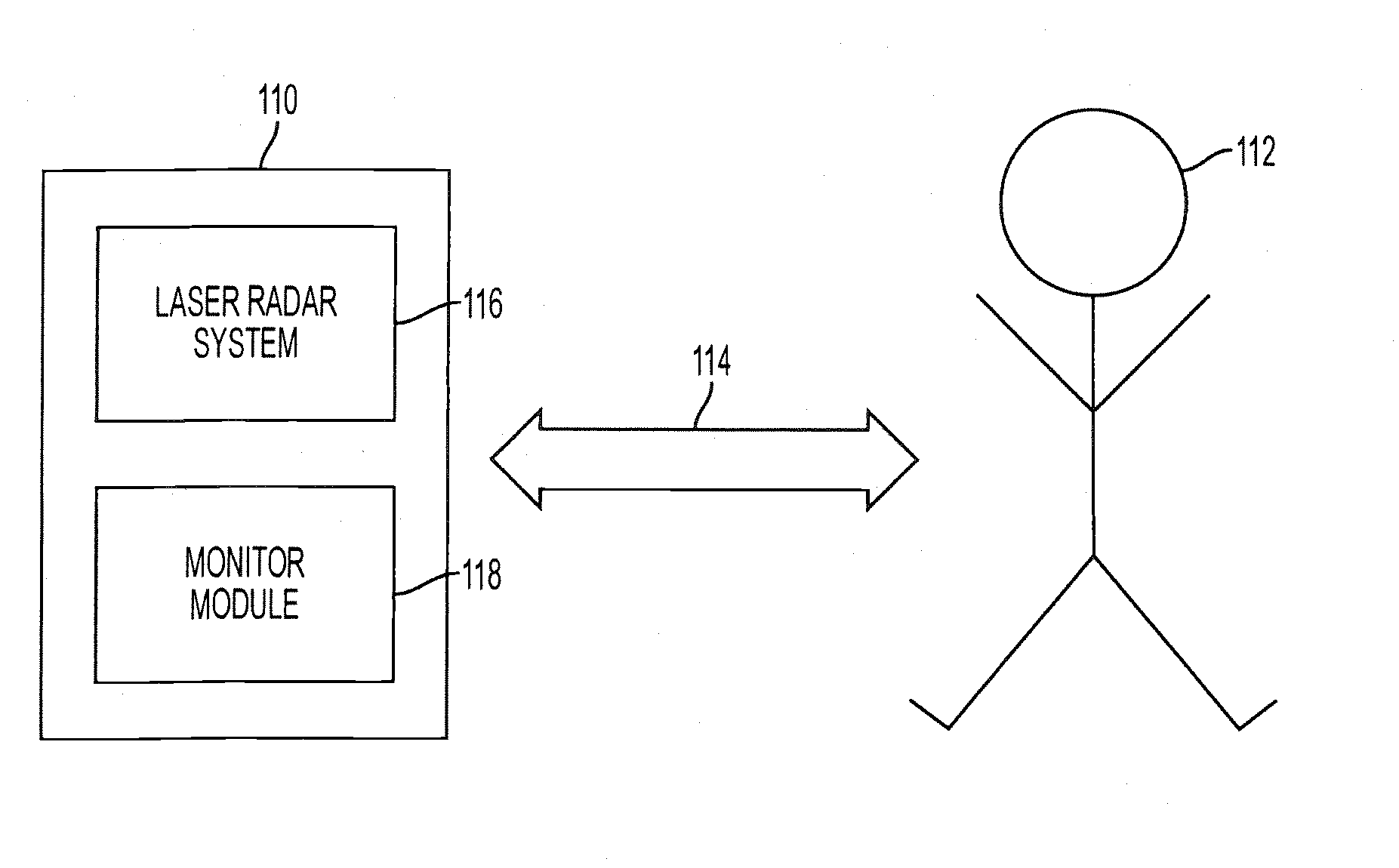
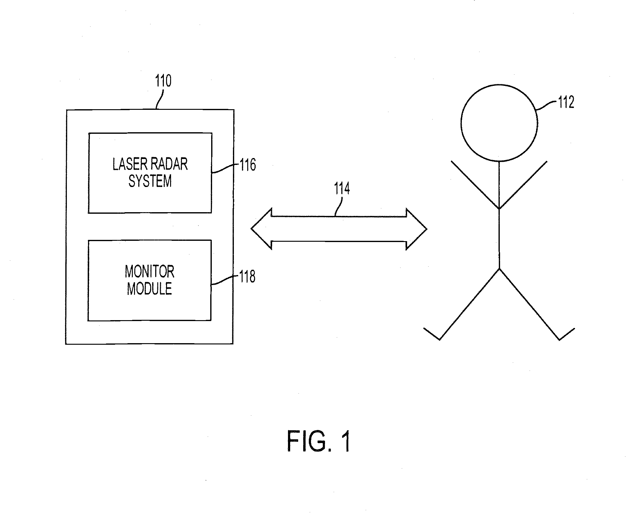
[0040]FIG. 1 is an exemplary illustration of a system 110 for detecting position information related to a face, and more particularly to an eyeball in a face of an individual 112, in accordance with some embodiments of the invention. System 110 may determine position information related to the eyeball of individual 112. System 110 may include a laser radar system 116 capable of determining a range to and / or a range rate (i.e., velocity) of a point on a surface of individual 112 (e.g., skin, clothing, lips, etc.). System 110 may include a monitor module 118 capable of determining position information related to the eyeball of individual 112 based on the determinations of laser radar system 116. System 110 may enable the position information related to the eyeball of individual 112 to be monitored and determined remotely from individual 112 without directly contacting individual 112.

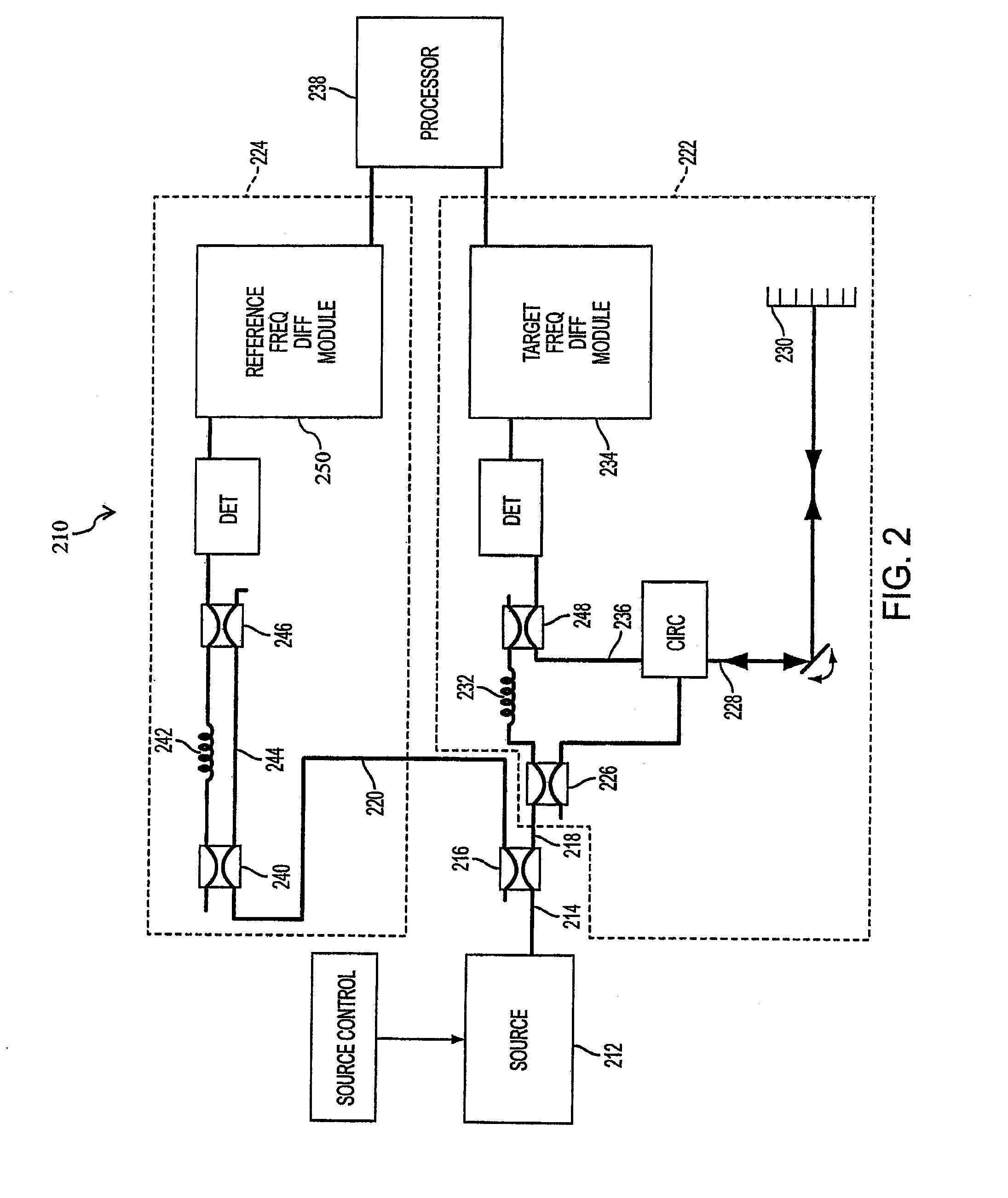
[0041]In some embodiments of the invention, laser radar system 116 may direct a beam of electromagnetic...


PUM


Abstract

Detecting position information related to a face, and more particularly to an eyeball in a face, using a detection and ranging system, such as a Radio Detection And Ranging (“RADAR”) system, or a Light Detection And Ranging (“LIDAR”) system. The position information may include a location of the eyeball, translational motion information related to the eyeball (e.g., displacement, velocity, acceleration, jerk, etc.), rotational motion information related to the eyeball (e.g., rotational displacement, rotational velocity, rotational acceleration, etc.) as the eyeball rotates within its socket.

Description

RELATED APPLICATIONS[0001]This application claims priority from U.S. Provisional Patent Application No. 60 / 750,045, entitled “System and Method for Tracking Eyeball Motion,” filed Dec. 14, 2005, the contents of which are incorporated herein by reference. This application is related to U.S. Provisional Patent Application No. 60 / 651,989, entitled “Chirped Coherent Laser Radar System and Method,” filed Feb. 14, 2005, the contents of which are incorporated herein by reference.FIELD OF THE INVENTION[0002]The invention relates generally to tracking the movement of an eyeball, and more particularly to tracking the movement of an eyeball using a detection and ranging system.BACKGROUND OF THE INVENTION[0003]Determining the motion of an eyeball of an individual may have practical application in a multitude of environments. For example, eyeball motion may be monitored in iris and / or corneal recognition systems, stimulus response measurement, medical procedures, virtual reality systems, or othe...

Claims


Application Information

Patent Timeline
Patent Type & Authority Patents(United States)
IPC IPC(8): A61B3/14G01S17/86
CPCA61B3/00A61B3/113G01S13/88A61B3/14A61B3/145G01S17/89G01S17/88G01S17/86A61B5/0077A61B5/11
Inventor SEBASTIAN, RICHARD L.BELSLEY, KENDALL L.
Owner AEVA INC
Why Eureka
Try Eureka