
Display hook assembly having a secure free end

a display hook and free end technology, applied in the direction of keys, machine supports, locks, etc., can solve the problems of not being immediately accessible to would-be thieves, would-be thieves, and being more difficult to access the locking mechanism to disengage the sam

Inactive Publication Date: 2010-04-27
INVUE SECURITY PROD INC
View PDF27 Cites 32 Cited by
  • Summary
  • Abstract
  • Description
  • Claims
  • Application Information

AI Technical Summary

Benefits of technology

Effectively prevents the rapid removal of merchandise by requiring a specific dipole magnet key for unlocking, making it difficult for thieves to access the locking mechanism and reducing the likelihood of multiple items being removed simultaneously.

Problems solved by technology

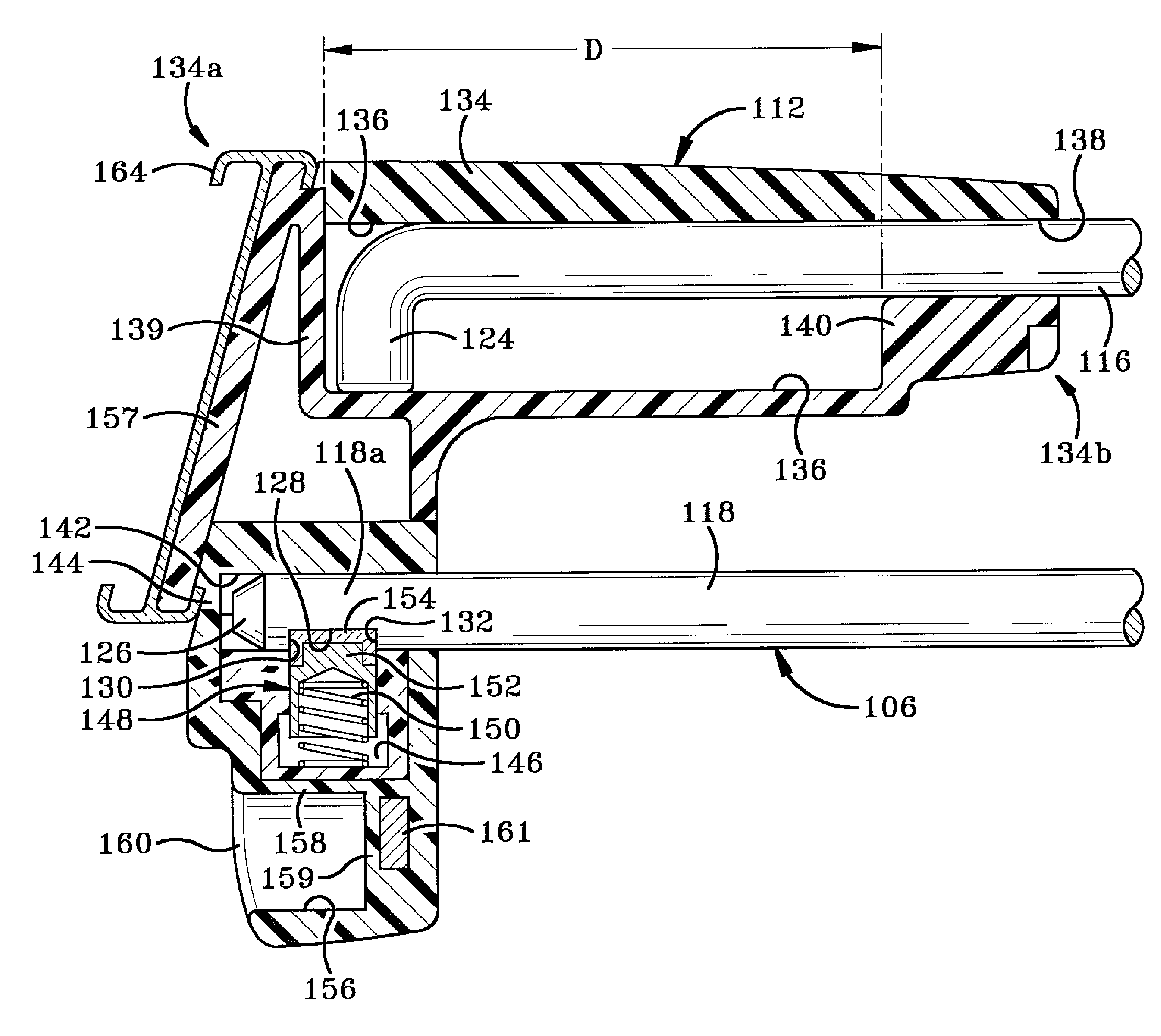
As the locking mechanism is contained within the interior of the end assembly, it is not immediately accessible to would-be thieves.
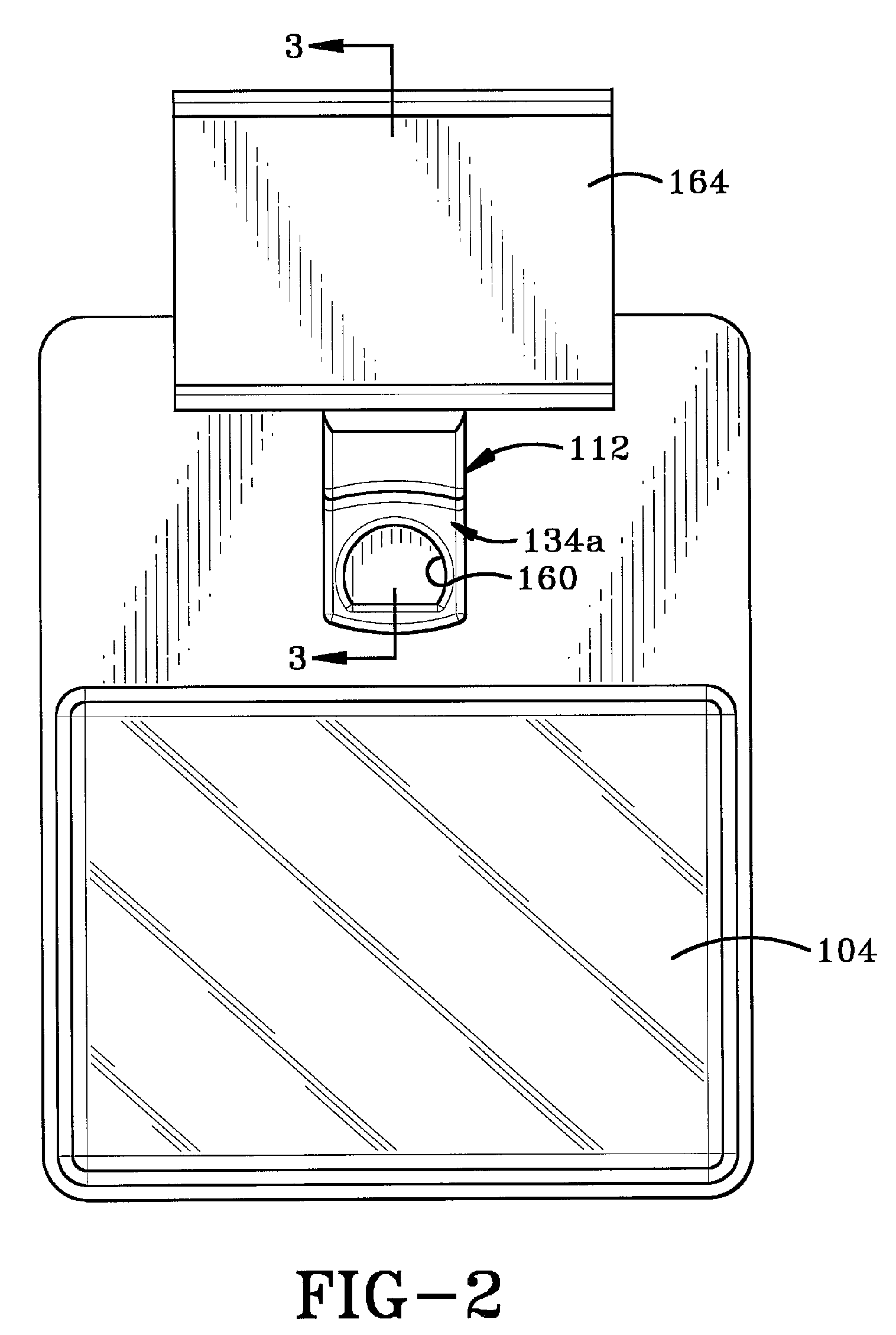
Furthermore, the complementary nature of the shaped recess and shaped dipole magnet key also hinders would-be thieves by making it more difficult to access the locking mechanism to disengage the same.
The locking mechanism itself is insulated from immediate access by a magnet and is oriented in such a manner that the force field from a common bar magnet will not easily move the locking mechanism within the interior chamber of the device.

Method used


Image

  • Display hook assembly having a secure free end
  • Display hook assembly having a secure free end
  • Display hook assembly having a secure free end

Examples


Embodiment Construction

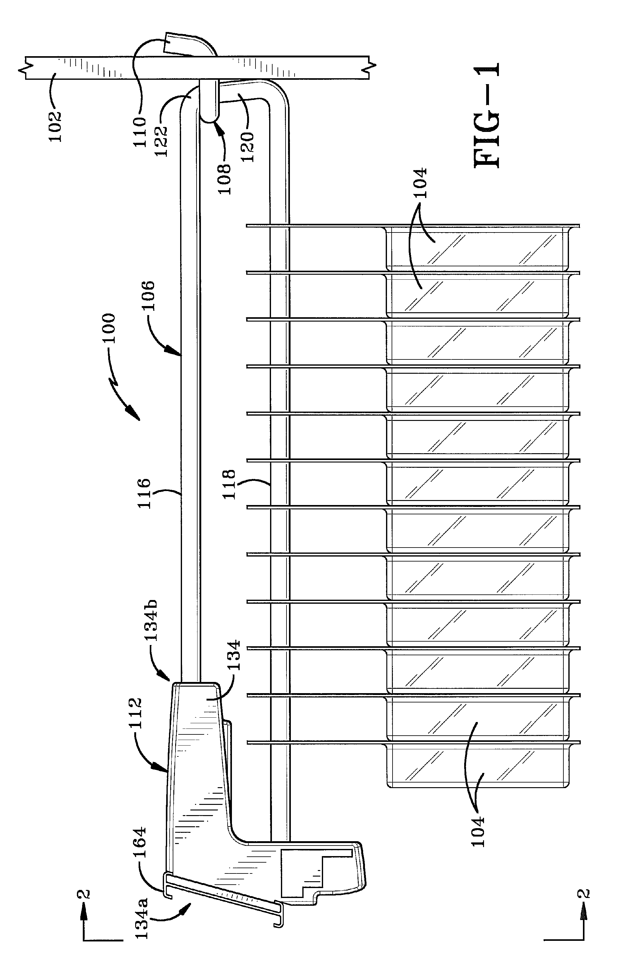
[0022]The merchandise display system of the present invention is indicated generally by the numeral 100, and is shown in FIGS. 1-8. Display system 100 is used with a display board 102 (peg board or slat board) to support merchandise 104 for display in a retail environment. Display system 100 comprises a rod assembly 106 and an end assembly 112. Rod assembly 106 includes substantially parallel first and second rods 116, 118 and a connecting rod 120 disposed therebetween. Rod assembly also includes an end 110 having one or more upwardly extending members that are receivable through holes in display board 102 to removably mount rod assembly 106 thereto in a cantilevered manner. Merchandise 104 is slidably engaged on second rod 118 and an end assembly 112 is provided to lockably secure merchandise 104 on second rod 118.

[0023]The present inventor is concurrently filing a U.S. patent application directed to a security device for lockably securing the rod assembly to the display board. Thi...


PUM


Abstract

A securable system for displaying items of merchandise on a display board. The display system includes a lockable end assembly that engages the free end of at least one rod of a merchandise display therein. The end assembly is slidable along the rod between an unlocked position where items of merchandise may be removed therefrom and a locked position where items of merchandise cannot be removed therefrom. The end assembly is lockingly engaged with the rod by a locking mechanism that is linearly moveable within an interior chamber of the end assembly. The end assembly is provided with a specially shaped recess in its outer wall which is positioned perpendicular to the linear motion of the locking mechanism. A complementary dipole magnet key is inserted into the recess to unlock the locking mechanism.

Description

CROSS-REFERENCE TO RELATED CASES[0001]This application is a standard utility application claiming priority from U.S. Provisional Application Ser. No. 60 / 879,899, filed Jan. 11, 2007, the entire disclosure of which is incorporated herein by reference.BACKGROUND OF THE INVENTION[0002]1. Technical Field[0003]This invention generally relates to merchandise display hooks that are attached to a display board or a wire display rack. More particularly, the present invention relates to display hooks that prevent the rapid removal of items of merchandise therefrom. Specifically, the invention relates to a security device for locking a merchandise display to prevent unauthorized removal of items of merchandise displayed thereon and to a system incorporating the same.[0004]2. Background Information[0005]Items of merchandise are commonly displayed for sale on long protruding rods supported from a peg board or slat board. These protruding rods are commonly referred to in the art as peg board hook...

Claims


Application Information

Patent Timeline
Patent Type & Authority Patents(United States)
IPC IPC(8): E05B65/00
CPCA47F5/0861Y10T70/7904Y10T70/7057Y10T70/5027Y10T70/5004
Inventor NAGELSKI, KEITH C.
Owner INVUE SECURITY PROD INC
Learn More