Fluid control valve

a technology of control valve and valve body, which is applied in the direction of valve details, flow control, instruments, etc., can solve the problems of noisy operation, high cost, and bulky valves, and achieve the effect of cost saving and performance benefits

Inactive Publication Date: 2010-04-27
CARDINAL HEALTH IRELAND UNLTD
View PDF28 Cites 16 Cited by
  • Summary
  • Abstract
  • Description
  • Claims
  • Application Information

AI Technical Summary

Benefits of technology

[0004]It is an object of the invention to provide a fluid control valve from which cost savings and performance benefits can be obtained compared with the prior art through, for example, injection moulding of miniaturised components.

Problems solved by technology

Such valves are often expensive and bulky, may require reasonable power to operate and can be noisy in operation due to moving parts and fluid flow through internal pathways.

Method used


Image

  • Fluid control valve
  • Fluid control valve
  • Fluid control valve

Examples


Embodiment Construction

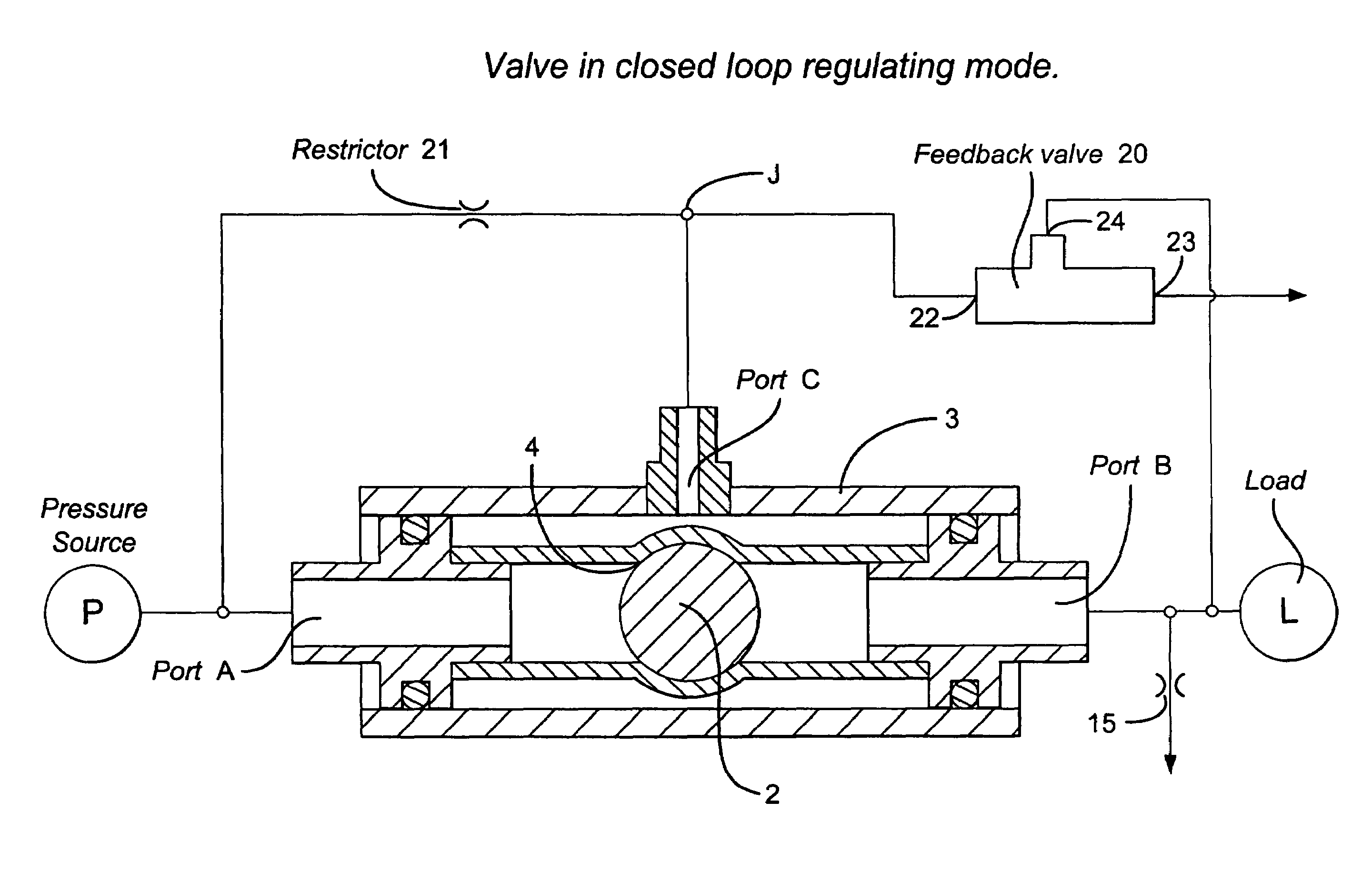
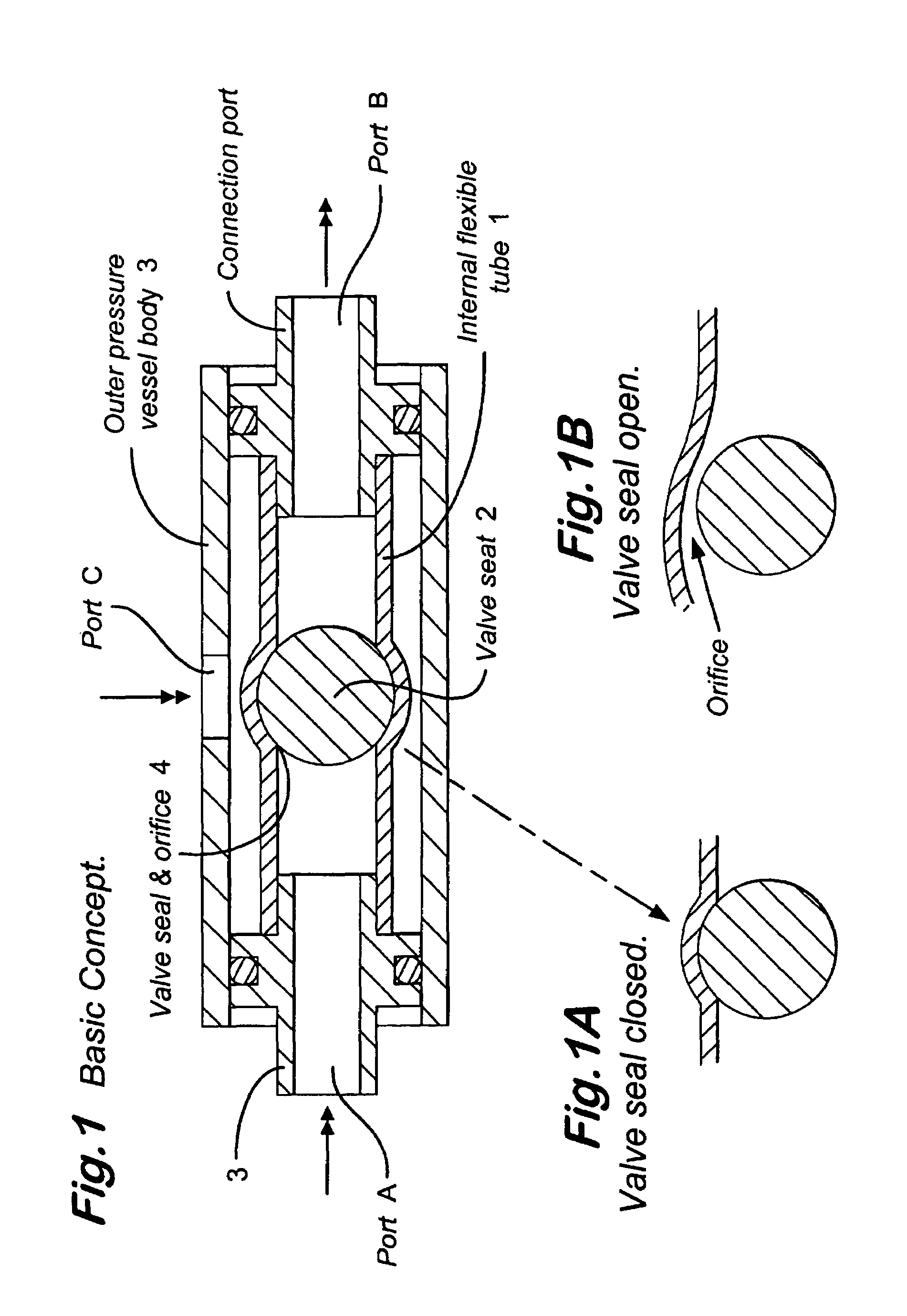
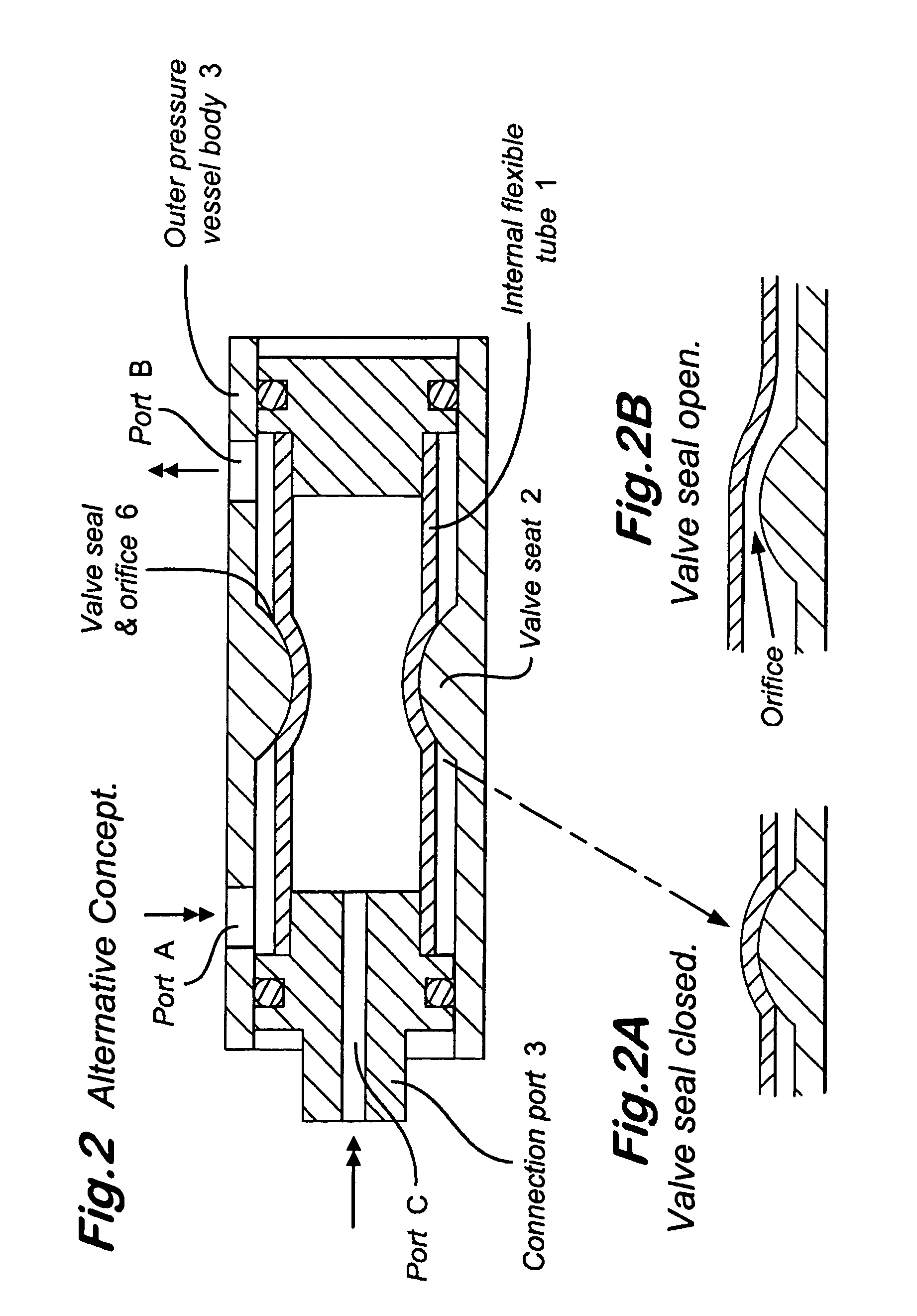
[0016]The valve shown in FIG. 1, 1A and 1B has an internal flexible tubular component 1 containing, and in immediate contact with, a spherical valve seat 2 retained between connection ports A, B at each end. The flexible tubular component 1 is contained within an outer pressure vessel 3 to which a further port C is connected.

[0017]A valve seal 4 is formed between the inner wall of the flexible tubular component 1 and the outer diameter of the valve seat 2. In the example shown see FIG. 1A the valve is configured as normally closed due to the valve seat 2 having a larger diameter than the bore of flexible tubular component 1.

[0018]In use the input or source pressure is connected to port A and the output connection taken from port B. The valve is controlled by application of pressure to port C. When the valve is operated fluid flows freely from port A to port B through the valve seal 4, opening as a complete or partial circumferential orifice between the flexible tubular component 1 a...


PUM


Abstract

A fluid control valve for use with apparatus for medical use. Commercially available valves which operate by electrical, hydraulic or pneumatic means are often expensive and bulky. They may require excessive power to operate them and can be noisy during operation due to moving parts and fluid flow through internal pathways. The valve of the present invention has a valve seal (1) mounted between inlet (A) and outlet ports (B), with the seal including a valve closure member (4) operated by means of a control fluid fed through a control port (C) in the valve body. In operation a pressure differential acting to open and close the valve is set up between the inlet and outlet ports and the control port to operate the valve. This design results in cost savings and performance benefits compared with the prior art.

Description

FIELD OF THE INVENTION[0001]The present invention relates to a fluid control valve and particularly to a fluid control valve for use with apparatus for medical use.BACKGROUND OF THE INVENTION[0002]The control of fluid is an essential element in the process and manufacturing industry or in applications where such conditions are utilised for the benefit or well being of mankind such as in medical apparatus.[0003]Valves are commercially available which operate by electrical, hydraulic or pneumatic means to open, close or regulate flow or pressure within acceptable parameters. Such valves are often expensive and bulky, may require reasonable power to operate and can be noisy in operation due to moving parts and fluid flow through internal pathways.SUMMARY OF THE INVENTION[0004]It is an object of the invention to provide a fluid control valve from which cost savings and performance benefits can be obtained compared with the prior art through, for example, injection moulding of miniaturis...

Claims


Application Information

Patent Timeline
Patent Type & Authority Patents(United States)
IPC IPC(8): F16K31/385F16K7/10A61M39/00F16K7/07G05D7/01G05D7/06
CPCG05D7/012F16K7/075Y10T137/7769Y10T137/7764
Inventor COOK, GORDONFOLLET, GRAEME
Owner CARDINAL HEALTH IRELAND UNLTD
Why Eureka
Try Eureka