Trajectory compensating sighting device systems and methods

a technology of trajectory compensation and sighting device, which is applied in the field of automatic determination and display of trajectory compensation crosshairs of riflescopes, can solve problems such as rifleman missing the intended target and affecting the flight of bullets

Active Publication Date: 2010-04-27
BURRIS
View PDF76 Cites 75 Cited by
  • Summary
  • Abstract
  • Description
  • Claims
  • Application Information

AI Technical Summary

Benefits of technology

[0007]The present invention relates to new and improved embodiments of sighting systems for visually acquiring a target. The sighting system comprises an optic device, such as a riflescope, having an aiming component in the optic device. The aiming component may include one or more LCD elements that are addressable by a controller to provide an aiming po

Problems solved by technology

In addition, some bullets travel at higher speeds than other bullets, which also affect the flight of the bullet.
Unfortunately, the hatches are generally not labeled and the rifleman must understand which hatch to use for his/her ne

Method used


Image

  • Trajectory compensating sighting device systems and methods
  • Trajectory compensating sighting device systems and methods
  • Trajectory compensating sighting device systems and methods

Examples


Embodiment Construction

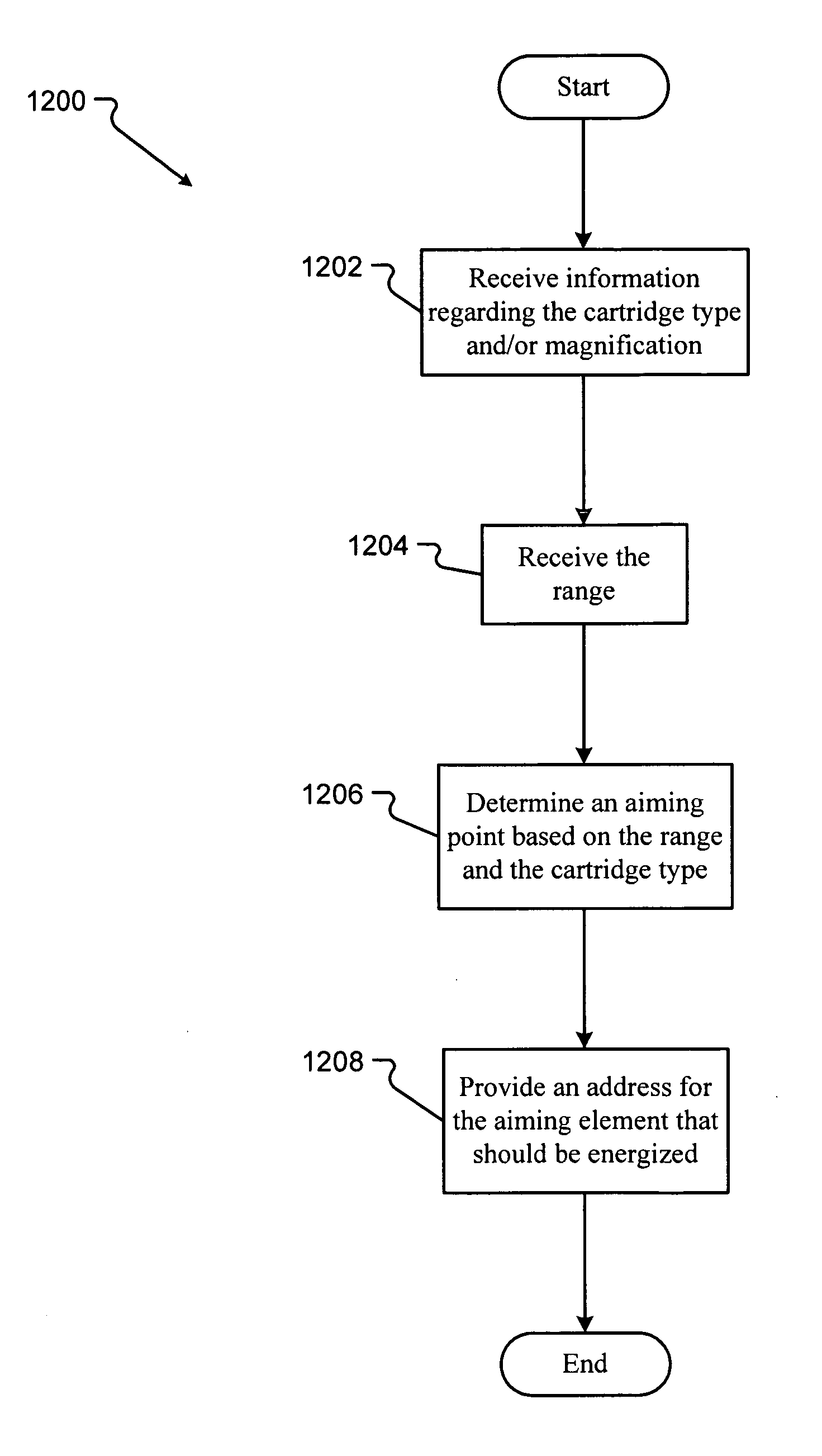
[0023]The present invention will now be described more fully hereinafter with reference to the accompanying drawings, in which embodiments of the invention are shown. The invention may, however, be embodied in many different forms and should not be construed as limited to the embodiments set forth herein. Rather, these embodiments are provided so that the disclosure will be thorough and complete and will fully convey the scope of the invention to those skilled in the art.

[0024]The present invention relates to new and improved embodiments of sighting systems and methods for correctly aiming a firearm or other implement. In embodiments, the sighting system includes an optic device, a range input, a controller / processor, an input system, a ballistics program, and an aiming component, possibly affixed to a lense of the optic device. The optic device is any device that can visually acquire a target, such as a riflescope. An exemplary riflescope may be the Euro Diamond 2.5×-10×-44 mm Matt...


PUM


Abstract

A sighting system for visually acquiring a target includes an optic device having a transmissive LCD array affixed thereon. The transmissive LCD array includes two or more LCD elements that are separately addressable to provide an aiming point. In embodiments, the sighting system receives information from an input system, such as ammunition information or environmental information, executes a ballistics program to determine ballistics information using the received information, and determines a range to the target. A controller calculates an aiming point using the ballistics information and the target range. The controller then addresses or energizes one of the LCD elements to provide the aiming point.

Description

TECHNICAL FIELD[0001]The present invention relates generally to the field of devices that visually acquire targets. More particularly, the invention relates to the automatic determination and display of a trajectory compensating crosshair for a riflescope.BACKGROUND OF THE INVENTION[0002]Aiming a rifle or gun requires the consideration of several environmental and other types of factors. When a bullet travels from a rifle to an intended target, several forces affect the flight of the bullet. Gravity causes the bullet to drop in elevation as the bullet travels from the firearm to the target. If a hunter is close to his / her target, as shown in FIG. 1A, the bullet drops very little, represented by the adjusted trajectory 100. However, improvements in firearms and ammunition have allowed hunters to target game from long distances. At these greater distances, gravity causes a bullet to drop in elevation more significantly, as represented by the adjusted trajectory 102 in FIG. 1B. Other f...

Claims


Application Information

Patent Timeline
IPC IPC(8): G06K7/10
CPCF41G1/38F41G3/06F41G3/02F41G1/473
Inventor BENNETTS, STEVEN ANTHONYBARKDOLL, KENNETH LAWRENCE
Owner BURRIS
Why Eureka
Try Eureka