Quick coupling

a technology of coupling and coupling rod, which is applied in the direction of hose connection, pipe/joint/fitting, soil-shifting machine/dredger, etc., can solve the problems of increasing weight and construction size, and lateral forces can arise, and achieve compact design

Active Publication Date: 2010-04-27
LEIBHERR HYDRAULIKBAGGER GMBH
View PDF15 Cites 19 Cited by
  • Summary
  • Abstract
  • Description
  • Claims
  • Application Information

AI Technical Summary

Benefits of technology

[0005]It is therefore the object of the present invention to provide a quick coupling which is simple to operate, has a compact and favorably priced design and nevertheless permits a secure and low-wear connection of pressure media feeds.

Problems solved by technology

A disadvantage of this construction lies in the fact that the curved engagement slots generate a force component transversely to the coupling direction in the coupling procedure and that additional lateral forces can arise in that the couplings are not arranged pair-wise at both sides of the pivot axis of the clamping levers.
A further disadvantage of the known construction lies in the fact that, with large nominal widths, the very large forces have to be transmitted via the collet chucks and the latter have to be given a relatively large dimension for this reason.
This circumstance requires very wide engagement slots which are then reflected in the supporting cross-section and in the diameter of the clamping levers, which increases the weight and the size of the construction.

Method used


Image

  • Quick coupling
  • Quick coupling
  • Quick coupling

Examples


Embodiment Construction

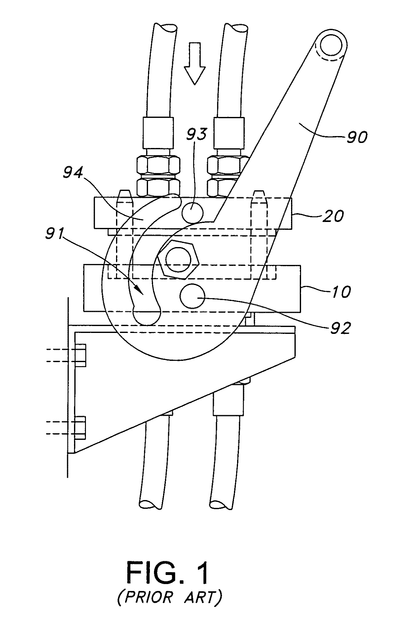
[0047]FIG. 1 shows a quick coupling in accordance with the prior art. This also has a base plate 10 and a support plate 20 to which the pressure media feeds to be connected are attached. Collect chucks 90 are rotatably supported at coaxial pivot bearing spigots 92 on both sides at the base plate 10. The collet chucks 90 have curved engagement slots 91 with which they engage over collet chucks 93 projecting from the edges of the support plate 20 coaxially to one another and parallel to the pivot bearing spigots 92. The disadvantage in this construction is that the curved engagement slots 91 generate a force component transversely to the coupling direction on the coupling process and lateral forces can additionally arise in that the couplings are not arranged pair-wise at both sides of the pivot axis of the collet chucks 90. Furthermore, on the coupling, the support plate 20 which is very heavy at large nominal widths, must be held with the one hand, while the collet chuck 90 is actua...


PUM


Abstract

The invention relates to a quick coupling comprising a base plate and a support plate, with the mounting frame being guided movably at the base plate and having means for connection to the support plate. In accordance with the invention, the support plate is moved toward the base plate by means of the mounting frame to close the coupling.

Description

BACKGROUND OF THE INVENTION[0001]The present invention relates to a quick coupling for the connection of pressure media feeds in a hydraulic system. Such quick-couplings are in particular used in the connection of pressure media feeds to hydraulically operated construction machinery, e.g. to connect an implement of the construction machine to the pressure supply fast and easily.[0002]Quick couplings are known for the connection of pressure media feeds which comprise a base plate and a support plate on which the pressure media feeds to be connected in each case are arranged. Clamping levers are pivotally supported around coaxial pivot bearing spigots on the base plate of such a known quick coupling, whereas clamping spigots are arranged parallel to the pivot bearing spigots on the support plate. The clamping lever has curved engagement slots with which it engages over the clamping spigots projecting beyond the support plate to close the coupling.[0003]To close the quick coupling, the...

Claims


Application Information

Patent Timeline
Patent Type & Authority Patents(United States)
IPC IPC(8): F16L37/00
CPCE02F9/2275F16L37/56Y10S285/92
Inventor ASAM, DIRKWACHTER, ROLANDWALTER, CHRISTIAN
Owner LEIBHERR HYDRAULIKBAGGER GMBH
Why Eureka
Try Eureka