
System and methodology providing coordinated and modular conveyor zone control

a conveyor and modular technology, applied in the direction of coupling device connection, contact member penetrating/cutting insulation/cable strand, instruments, etc., can solve the problems of speed and smoothness during conveyor operation, limited conveyor speed, and many problems with conventional distributed zone control systems, so as to facilitate rapid module installation and configuration, facilitate efficient and robust control of zone conveyer sections, and reduce cable and installation costs

Inactive Publication Date: 2010-04-27
ROCKWELL AUTOMATION TECH
View PDF42 Cites 36 Cited by
  • Summary
  • Abstract
  • Description
  • Claims
  • Application Information

AI Technical Summary

Benefits of technology

The present invention is a system and method for controlling multiple conveyor sections in a distributed conveyor assembly. The invention provides a modular system with sensing input, power output, communications, and control logic capabilities in a single module that can be easily installed and configured along conveyor sections. The modules can be connected together using a flat cable and vampire pins, which makes installation and configuration along the conveyor sections easy and cost-effective. The invention also includes a sophisticated signaling system that provides high immunity to electrical noise and can detect and respond to jam or sleep conditions. The invention also provides access for temporary connection of modules without using permanent vampire connections, and different types of zone modules can be connected to the N-conductor cable. Overall, the invention simplifies the process of configuring and controlling conveyor sections in a distributed conveyor assembly.

Problems solved by technology

Several problems currently exist with conventional distributed zone control systems, however.
One such problem relates to transmission line issues (e.g., reflections, noise) as a plurality of control stations can be concatenated for larger conveyor lines.
Other problems relate to cable and associated installation expenses when adding additional stations to an existing line or in the initial design and installation of the conveyor line itself.
Still yet another problem involves speed and smoothness during conveyor operations.
Due to communications limitations between zones, conveyor speed generally must be limited to avoid causing instabilities in the overall conveyor and associated control process.
Although centralized industrial controllers can be effective in controlling a conveyor line, these type solutions can add significant expense to a conveyor system.

Method used


Image

  • System and methodology providing coordinated and modular conveyor zone control
  • System and methodology providing coordinated and modular conveyor zone control
  • System and methodology providing coordinated and modular conveyor zone control

Examples


Embodiment Construction

[0042]The present invention relates to conveyor control system(s) and / or method(s), which may be operatively coupled with other such systems in order to implement a control strategy for a modular conveyor system. A module and / or series of modules are provided that clamp to a cable (e.g., flat four-conductor cable, and / or bridge to other media than cable), the modules having associated logic and inter-module communications for control. This includes relatively inexpensive power distribution, interconnection (such as for example to photoelectric sensors and actuators such as air valves or motor controllers) and motion logic for industrial conveyor systems.

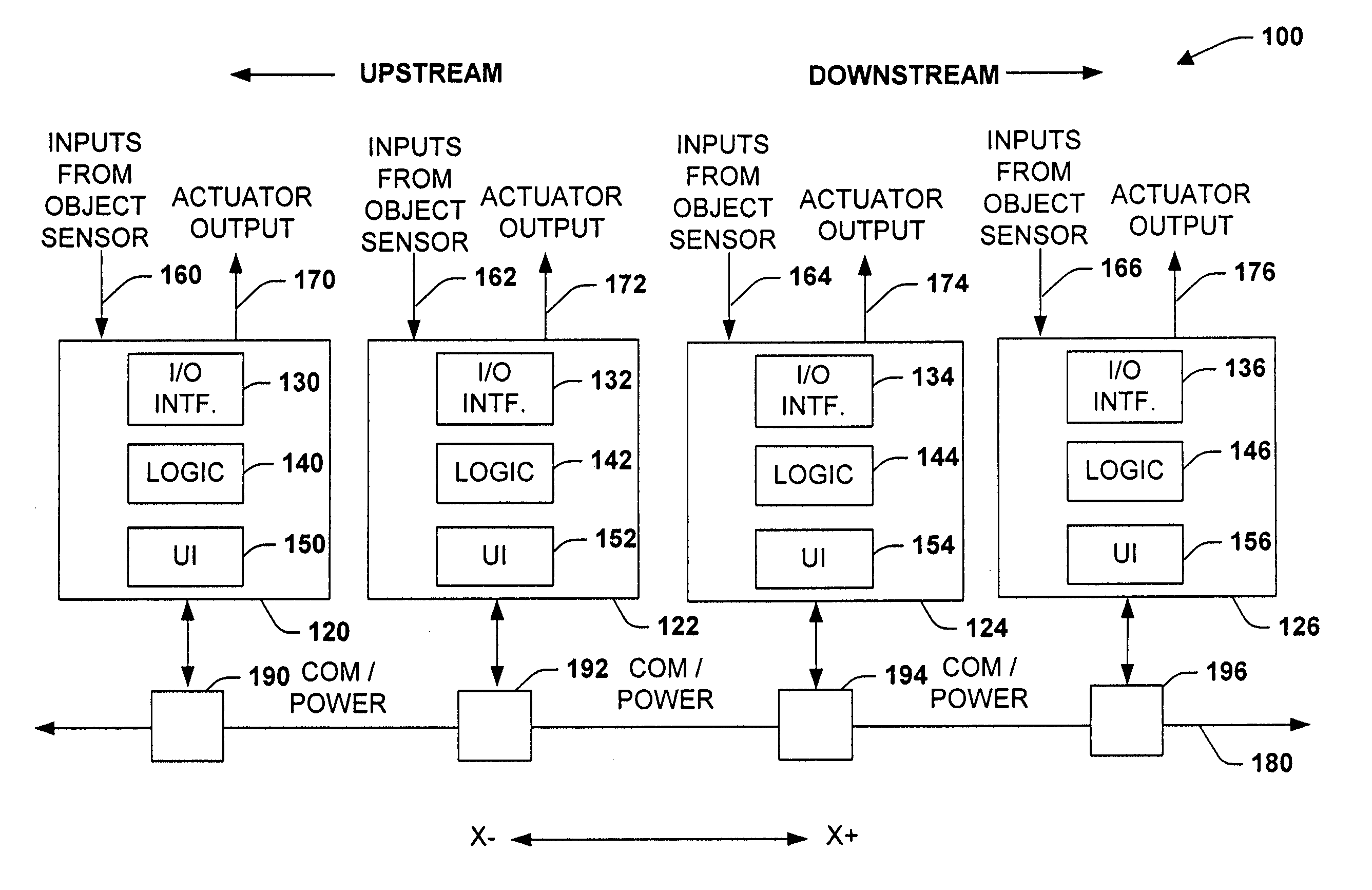
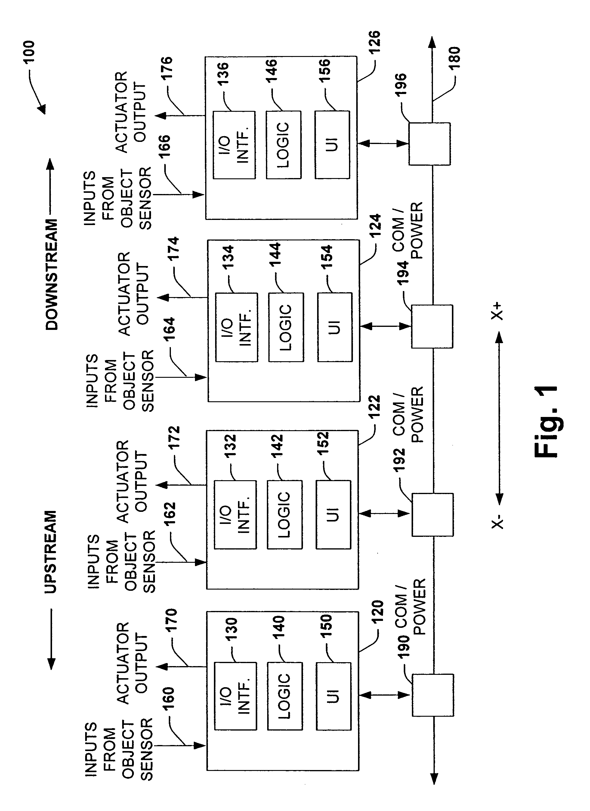
[0043]Referring initially to FIG. 1, a multi-zone conveyor system 100 is illustrated in accordance with an aspect of the present invention. The system 100 generally includes a plurality of zone modules 120-126 that cooperate to control associated conveyor sections (not shown). This can include Y upstream zone modules (Y being an inte...


PUM


Abstract

The present invention relates to conveyor control system and methodology that may be operatively coupled with other such systems in order to implement a control strategy for a modular conveyor system. A module and / or series of modules are provided that clamp to a cable, the modules having associated logic and inter-module communications for control. This includes relatively inexpensive power distribution, interconnection and motion logic for industrial conveyor systems.

Description

REFERENCE TO RELATED APPLICATION[0001]This application is a divisional of U.S. patent application Ser. No. 10 / 219,126, filed on Aug. 15, 2002, entitled “SYSTEM AND METHODOLOGY PROVIDING COORDINATED AND MODULAR CONVEYOR ZONE CONTROL,” which claims the benefit of U.S. Provisional Patent Application Ser. No. 60 / 356,485, filed on Nov. 13, 2001, entitled “SENSING SYSTEM AND METHOD,” the entireties of which are incorporated herein by reference.TECHNICAL FIELD[0002]The present invention relates generally to industrial control systems, and more particularly to a system and methodology to facilitate distributed and efficient control of a modular conveyor system.BACKGROUND OF THE INVENTION[0003]Control systems are often employed in association with conveyor systems for moving objects along guided tracks, including modular conveyor sections or “sticks”. Conveyor systems for moving objects between stations in a manufacturing environment or for accumulating and distributing products in a warehou...

Claims


Application Information

Patent Timeline
Patent Type & Authority Patents(United States)
IPC IPC(8): G08B21/00H01R4/24H01R25/14
CPCH01R4/2404H01R25/145Y10S439/912Y10S439/948H01R4/2406
Inventor DELANEY, III, PATRICK J.BYCZKIEWICZ, BARBARA JANINAGRINBERG, ANATOLY G.
Owner ROCKWELL AUTOMATION TECH
Learn More