
Liquid crystal display panel and method of driving the same

a technology of liquid crystal display panel and driving method, which is applied in the direction of electric digital data processing, instruments, computing, etc., can solve the problems of motion blurring phenomenon and the lack of ac driving method

Inactive Publication Date: 2010-04-27
LG DISPLAY CO LTD
View PDF1 Cites 10 Cited by
  • Summary
  • Abstract
  • Description
  • Claims
  • Application Information

AI Technical Summary

Benefits of technology

The present invention provides a liquid crystal display panel and method of driving it that overcomes the limitations and disadvantages of existing technologies. The panel includes first and second pixel electrodes on a first substrate with an insulating film therebetween, and a common electrode on a second substrate that is bonded with the first substrate with a liquid crystal therebetween. The panel selectively applies a maximum voltage and a minimum voltage to the first pixel electrode, a medium voltage to the common electrode, and a positive and negative data voltage to the second pixel electrode. The panel also includes a thin film transistor and a drive circuit for supplying the positive and negative data voltages. The invention provides a more efficient and effective way to drive liquid crystal displays.

Problems solved by technology

The related art liquid crystal display panel has a disadvantage in that a motion blurring phenomenon occurs because of a slow response speed caused by the viscosity and elasticity of the liquid crystal.
However, the three electrode liquid crystal display panel should drive the liquid crystal with alternating current (AC) in order to prevent the liquid crystal from deteriorating, but the AC driving method has not yet been proposed.

Method used


Image

  • Liquid crystal display panel and method of driving the same
  • Liquid crystal display panel and method of driving the same
  • Liquid crystal display panel and method of driving the same

Examples


Embodiment Construction

[0059]Reference will now be made in detail to the preferred embodiments of the present invention, examples of which are illustrated in the accompanying drawings.

[0060]With reference to FIGS. 2 to 7B, embodiments of the present invention will be explained as follows.

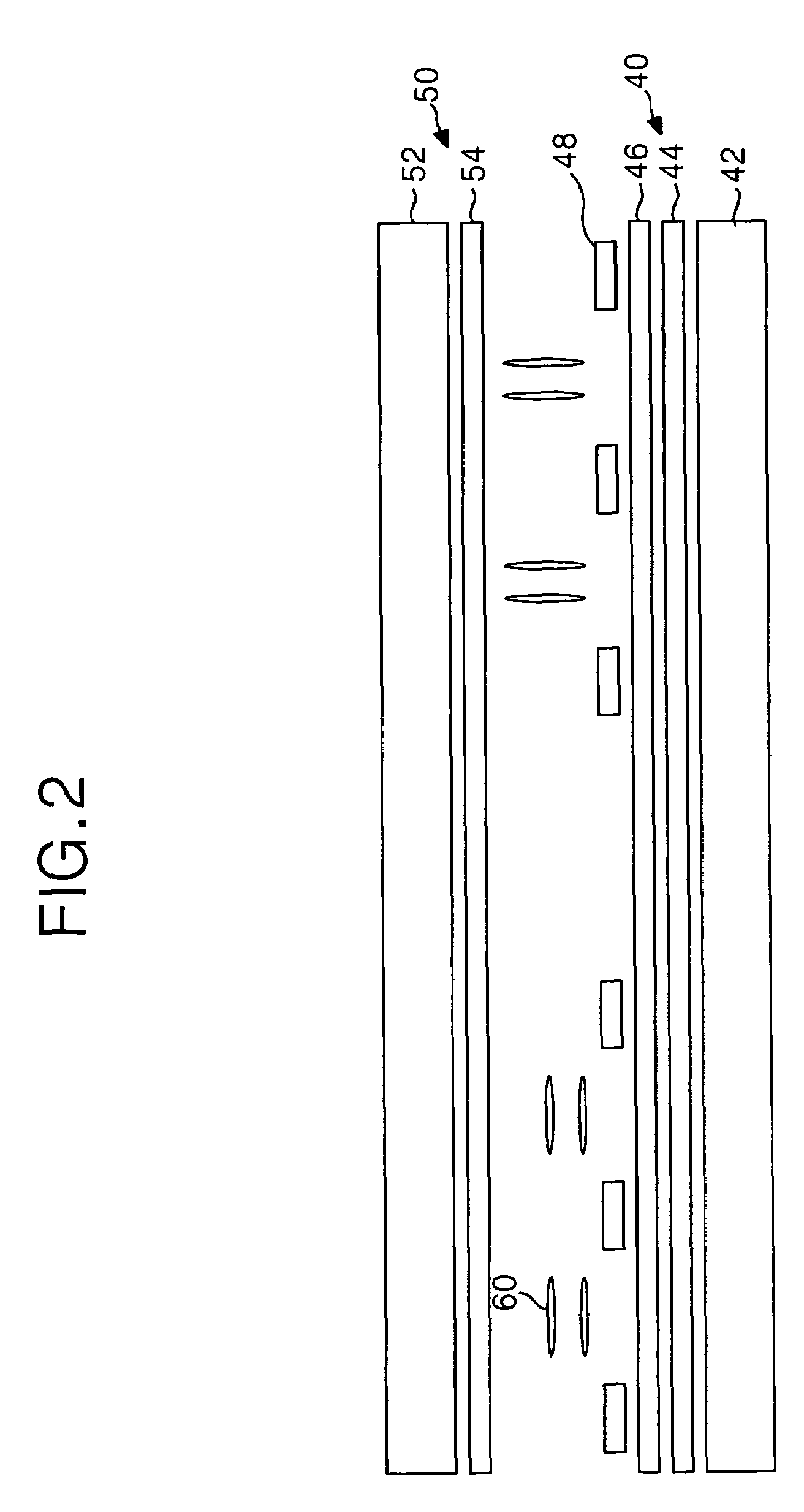
[0061]FIG. 2 is a sectional diagram illustrating two liquid crystal cell parts in a three electrode liquid crystal display panel according to an embodiment of the present invention.

[0062]The three electrode liquid crystal display panel shown in FIG. 2 includes a thin film transistor substrate 40 and a color filter substrate 50 that are bonded with a liquid crystal 60 therebetween.

[0063]The color filter substrate 50 includes a common electrode 54 formed of a transparent conductive layer over the entire surface of an upper substrate 52. A reference voltage V1 that is the standard value for driving a liquid crystal cell is supplied to the common electrode 54. The color filter substrate 50 further includes a color filter and ...


PUM


Abstract

This invention relates to a three electrode liquid crystal display panel that is adaptive for AC-driving liquid crystal cells inclusive of three electrodes, and a driving method thereof.A three electrode liquid crystal display panel according to an embodiment of the present invention includes first and second pixel electrodes disposed on a first substrate with an insulating film therebetween; and a common electrode disposed in a second substrate which is bonded with the first substrate with a liquid crystal therebetween, and wherein the first pixel electrode selectively supplies a maximum voltage and a minimum voltage, the common electrode supplies a medium voltage between the maximum voltage and the minimum voltage as a reference voltage, and the second pixel electrode supplies a positive data voltage and a negative data voltage on the basis of the reference voltage in a range between the maximum voltage and the minimum voltage, thereby AC-driving the liquid crystal.

Description

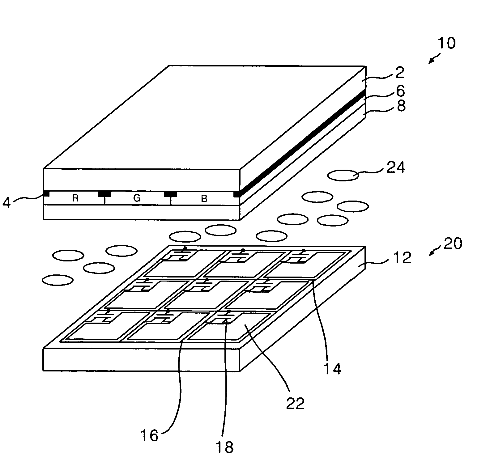
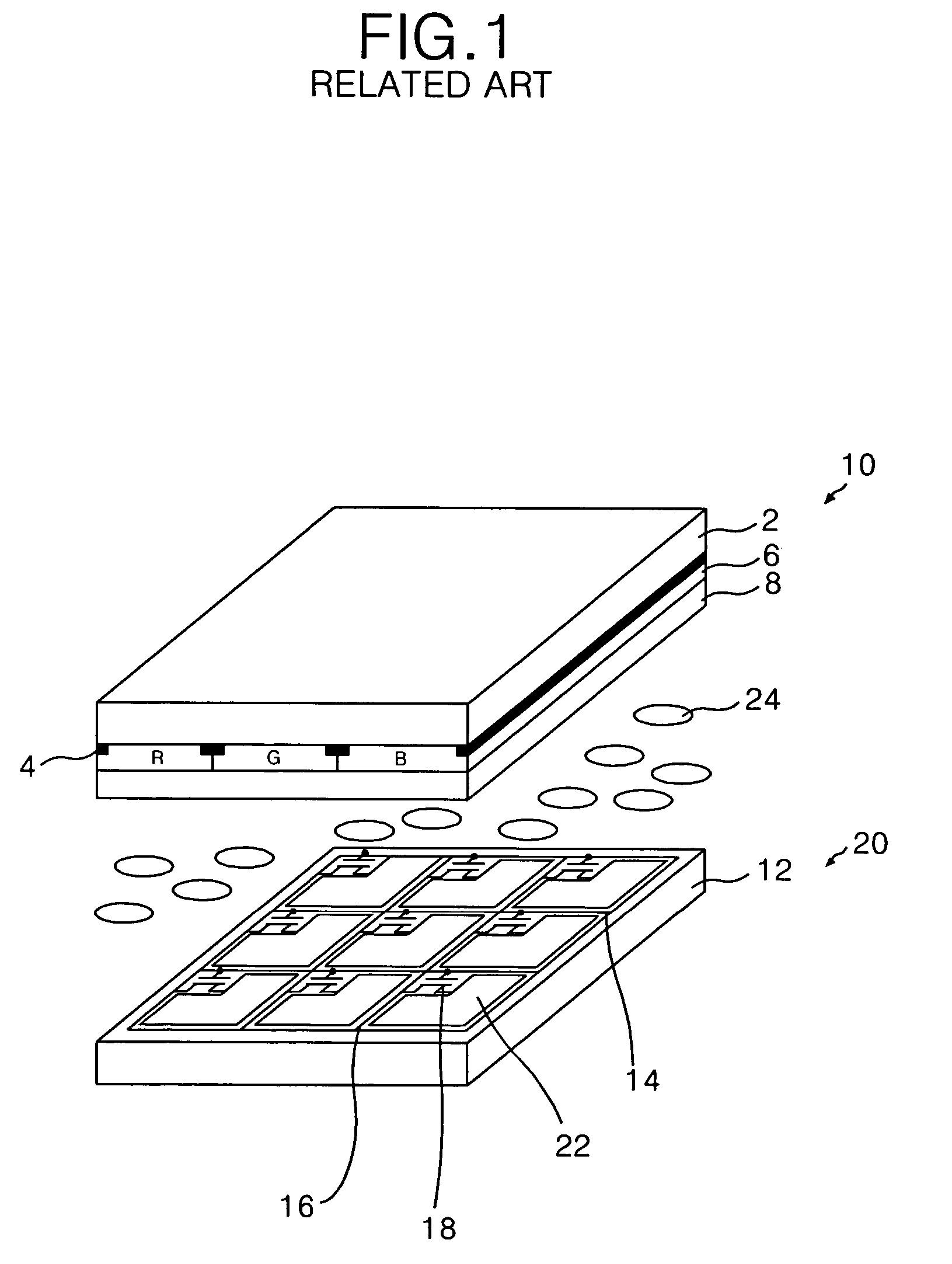
[0001]This application claims the benefit of the Korean Patent Application No. P2004-118562 filed on Dec. 31, 2004, which is hereby incorporated by reference for all purposes as if fully set forth herein.BACKGROUND OF THE INVENTION[0002]1. Field of the Invention[0003]The present invention relates to a liquid crystal display device, and more particularly to a liquid crystal display panel using three electrodes, and a driving method thereof.[0004]2. Discussion of the Related Art[0005]A liquid crystal display device controls the light transmittance of a liquid crystal having a dielectric anisotropy using an electric field, thereby displaying a picture. The liquid crystal display device includes a liquid crystal display panel that displays a picture through a liquid crystal cell matrix, and a drive circuit for driving the liquid crystal display panel.[0006]Referring to FIG. 1, a liquid crystal display panel of the related art includes a color filter substrate 10 bonded to a thin film tr...

Claims


Application Information

Patent Timeline
Patent Type & Authority Patents(United States)
IPC IPC(8): G09G3/36
CPCG02F1/1368G09G3/3655G02F2001/134381G09G2320/0252G09G3/3614G02F1/134381G02F1/133
Inventor HONG, HYUNG KI
Owner LG DISPLAY CO LTD
Learn More