
Industrial truck having increased static or quasi-static tipping stability

a technology of static or quasi-static tipping stability and industrial trucks, which is applied in the field of industrial trucks, can solve the problems of reducing the starting acceleration and/or driving speed already achieved, and speed is reduced to zero

Inactive Publication Date: 2010-04-27
LINDE MATERIAL HANDLING
View PDF60 Cites 25 Cited by
  • Summary
  • Abstract
  • Description
  • Claims
  • Application Information

AI Technical Summary

Benefits of technology

The invention is a control system for industrial trucks that prevents tipping accidents by monitoring static and dynamic factors such as lifting load, tilting angle, load torque, and driving speed. The system uses sensors and vehicle-specific information to determine the driving and load state and can adjust the operating speed, starting and braking acceleration, and driving direction to prevent tipping. The system can also prioritize reducing starting and braking acceleration to increase tipping stability. Overall, the invention improves safety and prevents accidents in industrial trucks.

Problems solved by technology

In the process, the control device has the effect of a limitation of the actual values which can be achieved or, in an extreme case, the effect of reducing the actual values already achieved as regards the operating speed, the starting and braking acceleration, and / or the driving speed.
In the individual case, this may mean, for example, that, when the industrial truck is at a standstill, the operator wishes to tilt the lifted load forward at a specific speed by actuating a control lever but the tilting speed is reduced to zero by the control device owing to an impermissibly high risk of tipping, i.e., the forward tilting movement is completely prevented.
The control device allows the lifting -operation (possibly at a reduced lifting speed) but reduces the starting acceleration and / or driving speed already achieved.

Method used


Image

  • Industrial truck having increased static or quasi-static tipping stability
  • Industrial truck having increased static or quasi-static tipping stability
  • Industrial truck having increased static or quasi-static tipping stability

Examples


Embodiment Construction

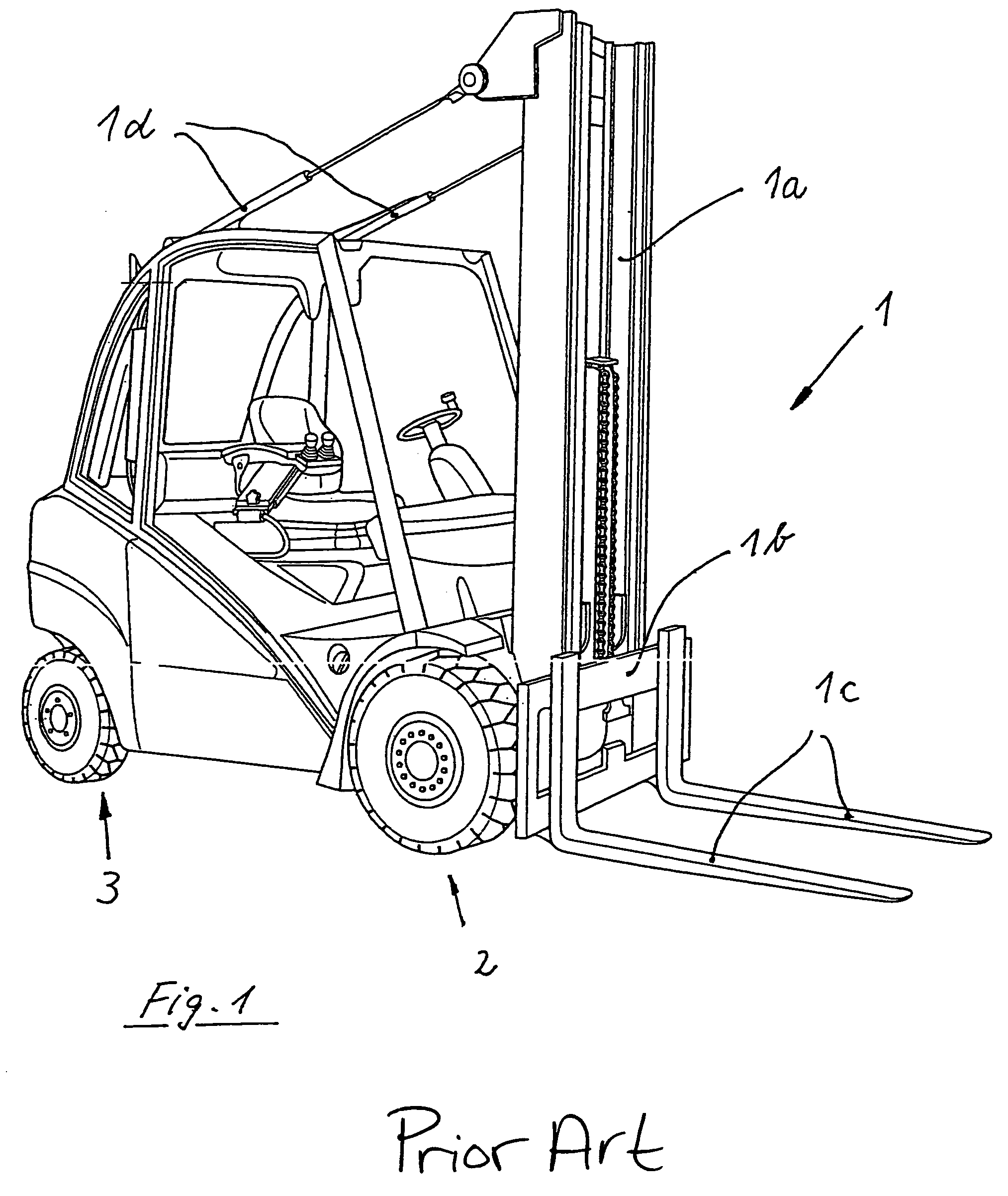
[0027]The industrial truck shown in FIG. 1 is in the form of a forward-control counterweight fork-lift truck. A load-lifting device 1 arranged on the vehicle front is formed by an extendable lifting mast 1a and a height-adjustable load carriage 1b on the lifting mast 1a having fork prongs 1c suspended in the load carriage 1b. With the aid of the fork prongs 1c, load goods of a variety of types can be lifted and transported.

[0028]The lifting mast la can be tilted about a horizontal axis arranged transversely in the lower region. Of course, it is also possible for a rigid, i.e., non-tiltable, lifting mast to be provided and, instead, the load carriage to be designed such that it is not only height-adjustable but is also tiltable, as is often the case, for example, with so-called warehousing devices (for example reach trucks). Other load-receiving devices may also be fixed to the load carriage 1b, depending on the intended use. It goes without saying that, in principle, additional move...


PUM


Abstract

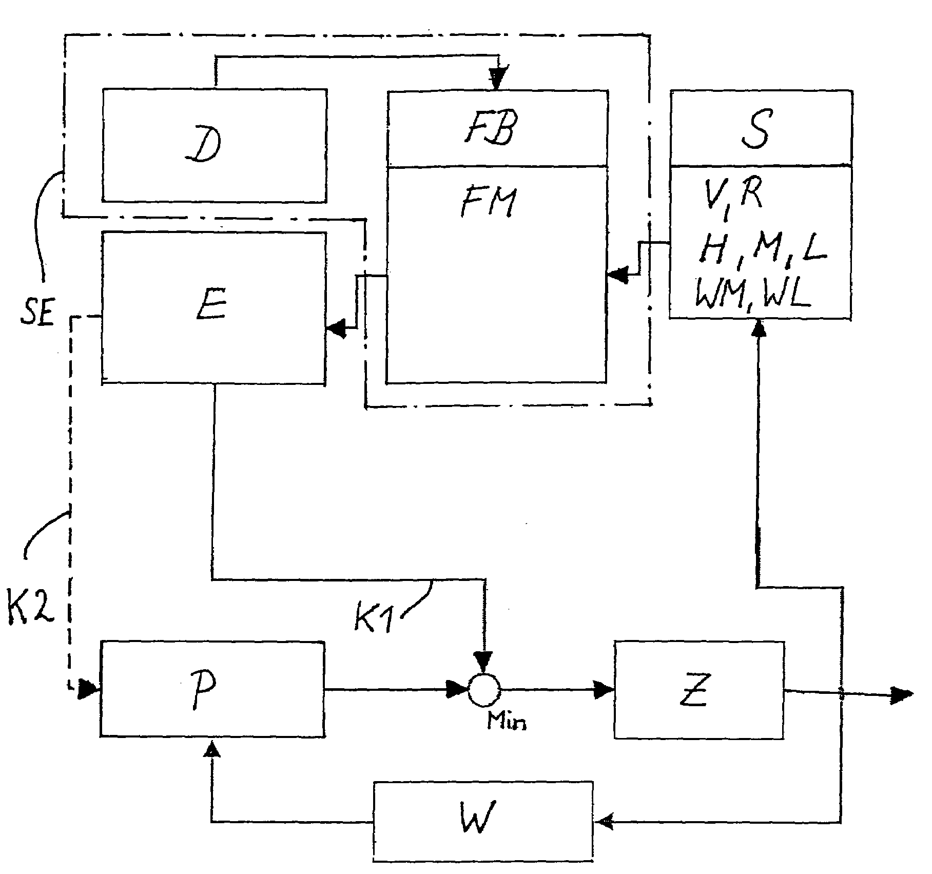
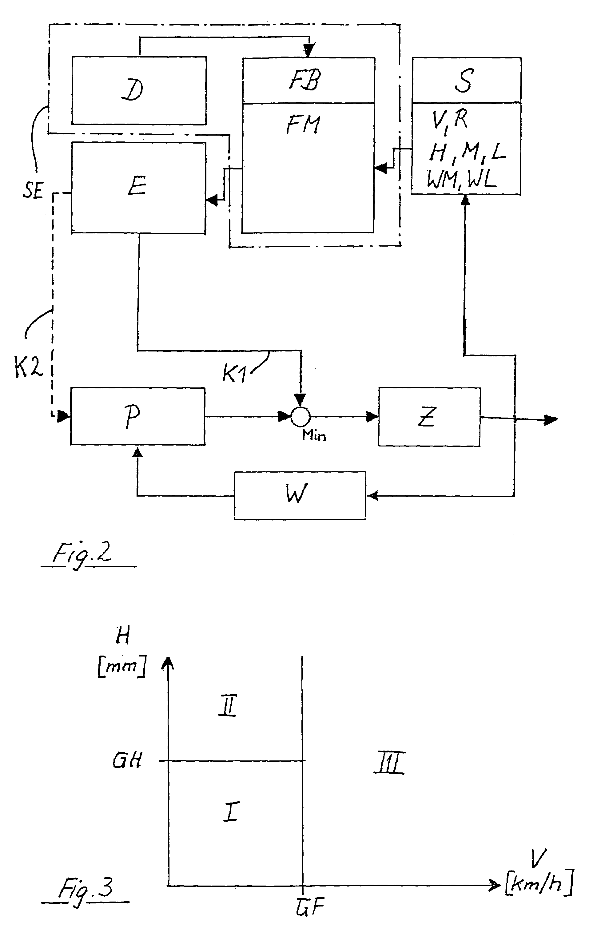
A forward-control counterweight fork-lift truck has a liftable and tiltable load-lifting device (1), a traction drive and operating drives for the movement of the load-lifting device (1). A calculation model (D) is stored in a control device (SE), to which directly or indirectly acting sensors (S) are connected for detecting the lifting load (L), the lifting height (H), the tilting angle (WM), the load torque (M), the direction of travel (R), the driving speed (V), and the steering angle (WL). The control device (SE) is designed to determine a driving and load state (Z) based on the detected physical variables (L, H, WM, M, R, V, WL) and the stored calculation model (D) and is operatively connected to the traction drive and the operating drives. Depending on the driving and load state (Z) determined, the operating speed, starting and braking acceleration, and driving speed are each reduced.

Description

CROSS-REFERENCE TO RELATED APPLICATION[0001]This application claims priority to German Application No. 10 2004 017 056.8 filed Apr. 7, 2004, which is herein incorporated by reference in its entirety.BACKGROUND OF THE INVENTION[0002]1. Field of the Invention[0003]The invention relates to an industrial truck, in particular a forward-control counterweight fork-lift truck, having a liftable and tiltable load-lifting device, a traction drive, and operating drives for movement of the load-lifting device.[0004]2. Technical Considerations[0005]In the case of conventional industrial trucks, the operator has to estimate the weight of the load goods to be lifted (lifting load) and the height to which the load goods are to be lifted (lifting height). On the basis of this, the driving speed and the turning radius of the industrial truck must be set such that there is no tipping of the industrial truck to the front or to the side. Although this demanding task must be managed in a static or quasi-...

Claims


Application Information

Patent Timeline
Patent Type & Authority Patents(United States)
IPC IPC(8): B66F9/06B66C13/16B66F9/16G01G23/365B66F17/00B60K28/08B60K28/14B60K31/00B65G1/00B66F9/22
CPCB66F17/003B60K31/00B66F9/22
Inventor BOZEM, GERHARDCARLITZ, ANDREASGOTZ, BERNHARDROTH, JURGENSCHRODER, FRANK
Owner LINDE MATERIAL HANDLING
Learn More