Audio signal noise reduction device and method

a technology of noise reduction device and audio signal, which is applied in the direction of transducer details, speech analysis, instruments, etc., can solve the problems of difficult to hear any human voice, often failed real-time audio capture, etc., and achieve the effect of reducing long-lasting noise, reducing long-lasting noise, and increasing masking effects

Inactive Publication Date: 2010-05-04
SONY CORP
View PDF18 Cites 11 Cited by
  • Summary
  • Abstract
  • Description
  • Claims
  • Application Information

AI Technical Summary

Benefits of technology

[0010]The above-described noise, i.e., shock noise, touch noise, or click noise, is not always generated continuously but generated only with any accidental shock. The most noise is thus generated abruptly in the time range of about several mS to several tens of mS. The applicant of the invention has thus proposed, in JP-A-2005-303681 entitled “Noise Reduction Method and Device”, to utilize a masking phenomenon observed in the human sense of hearing to perform noise reduction effectively.
[0041]In the embodiments of the invention, an interpolation signal in the gap period is not only modulated in level but also changed in frequency characteristics so that the signal continuity can be retained, and the masking effects can be increased to a further degree.

Problems solved by technology

Since the time delay caused by the operation cannot be neglected, and the audio signals have to be delayed at the same time, the audio capturing often fails to be done in real time.
The human being hears no small sound behinda relatively large sound, e.g., people find it difficult to hear any human voice in noisy environment.

Method used


Image

  • Audio signal noise reduction device and method
  • Audio signal noise reduction device and method
  • Audio signal noise reduction device and method

Examples


Embodiment Construction

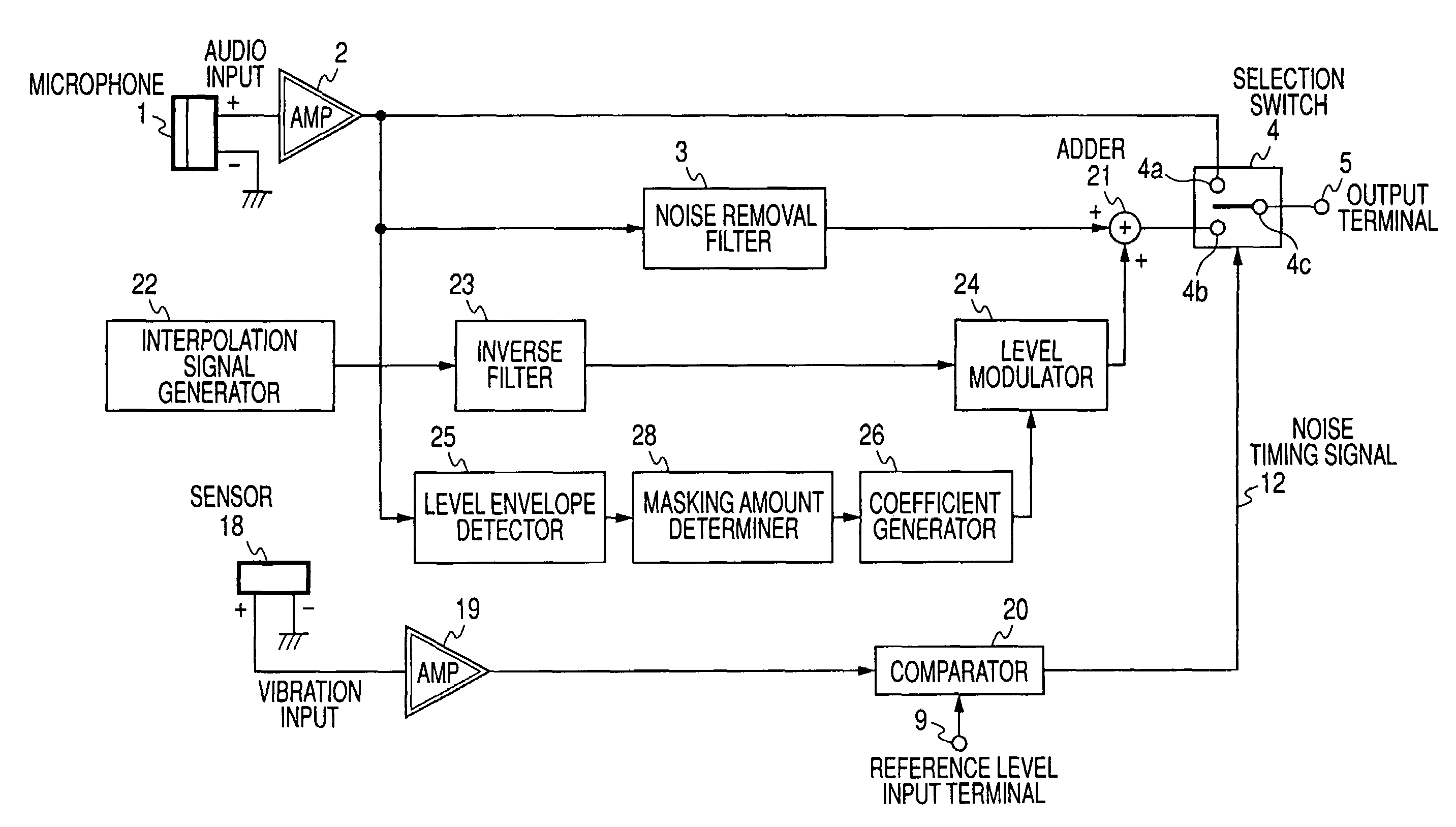
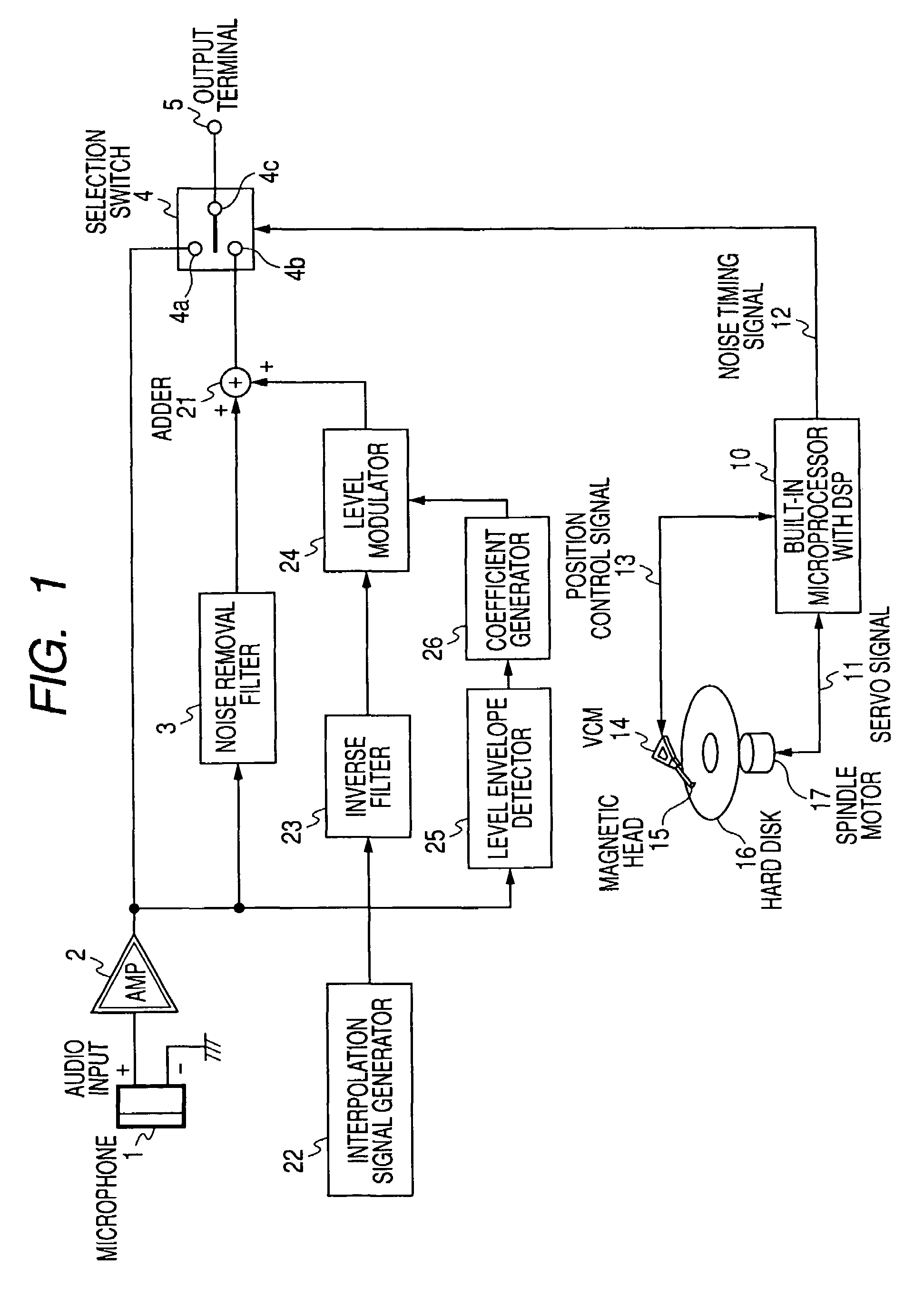
[0056]In the below, described is an exemplary best embodiment of the invention for a practical use of an audio signal noise reduction device and method by referring to the accompanying drawings. In FIG. 1, any component corresponding to that in FIG. 12 is provided with the same reference numeral, and not described in detail again.

[0057]In FIG. 1 example, similarly to FIG. 12 example, the noise timing signal 12 is generated by the built-in HDD-controlling microprocessor 10 with DSP, and serves as a control signal for the selection switch 4 as it is. At the time of a seek operation, the noise timing signal 12 works to control the movable contact point 4c of the selection switch 4 to be connected to the fixed contact point 4b thereof, and to select a signal coming from an adder 21. In the other timing, the noise timing signal 12 works to control the movable contact point 4c of the selection switch 4 to be connected to the fixed contact point 4a thereof, and to select an audio signal co...


PUM


Abstract

An audio signal reduction device that generates a gap period in accordance with a noise generation period of noise included in an input audio signal. Noise is removed from the audio signal, and the level envelope of the audio signal is continuously detected. A coefficient for the level envelope in the gap period is generated in accordance with the level envelope detection and is used to modulate an interpolated signal. The noise-removed audio signal and the modulated interpolated signal are mixed; and the mixed signal is output in a period corresponding to the gap period, while the audio signal is output, as is, not in the gap period.

Description

CROSS REFERENCES TO RELATED APPLICATIONS[0001]The present invention contains subject matter related to Japanese Patent Application JP 2005-342521 filed in the Japanese Patent Office on Nov. 28, 2005, the entire contents of which being incorporated herein by reference.BACKGROUND OF THE INVENTION[0002]1. Field of the Invention[0003]The invention relates to an audio signal noise reduction device that is equipped in a digital private electrical appliance, for example, and reduces the noise level of an audio signal captured by a small-sized microphone, and an audio signal noise reduction method.[0004]2. Description of the Related Art[0005]Digital private electrical appliances each including therein a small-sized microphone, e.g., video cameras, digital cameras, and IC recorders, are becoming increasingly smaller in size. Such a smaller-sized appliance often causes problems of arising unpleasant shock noise, touch noise, or click noise at the time of audio reproduction. Such noise is caus...

Claims


Application Information

Patent Timeline
Patent Type & Authority Patents(United States)
IPC IPC(8): G10L21/02
CPCG10L21/01G10L21/0208G10L21/0264G10L21/0232H04R3/00
Inventor OZAWA, KAZUHIKO
Owner SONY CORP
Why Eureka
Try Eureka