Lifting device having parallel double screw rods

a technology of double screw rods and lifting devices, which is applied in the direction of lifting devices, toothed gearings, and lifting devices, can solve the problems of inefficiency in reducing the total cost of elements, the conventional lifting device of screw rods cannot meet the requirement for a larger adjusting space, and the cost of components cannot be efficiently reduced. cost, the effect of simplifying the machining and heat treatment of primary members

Active Publication Date: 2010-05-11
TIMOTION TECH CO LTD
View PDF12 Cites 46 Cited by
  • Summary
  • Abstract
  • Description
  • Claims
  • Application Information

AI Technical Summary

Benefits of technology

[0008]The primary object of the present invention is to provide a lifting device having parallel double screw rods, in which the parallel arrangement of each screw rod makes it interchangeable, so that the machining and heat treatment of the primary members are simplified and the cost can be efficiently reduced.

Problems solved by technology

Since the total length of the extension of the lifting device does not exceed the sum of two sliding units and the total length of the retraction is not lower than the length of any one longer sliding unit, the extension and retraction stroke that is possibly achieved is limited and thus cannot satisfy the requirement for a larger adjusting space in the existing market.
Thus, it is an important issue for those skilled in this art to provide a connecting structure having a lifting device and a multiple-stage sliding unit.
However, in practical use, the conventional lifting device of screw rod has still some problems as follows.
Since the primary members such as the cylindrical screw rod and the pillared screw rod are manufactured separately, those elements cannot be interchangeable, so that the total cost of the elements cannot be reduced efficiently.
Further, the inside and outside of the cylindrical screw rod are provided with threads, the machining process is very complicated and difficult.
Also, after the machining process, it is not easy to perform the heat treatment to obtain a good surface hardness.
As a result, it is very fast to generate wear between the cylindrical screw rod and the pillared screw rod, causing the increase in the subsequent cost for maintenance and inconvenience in use.

Method used


Image

  • Lifting device having parallel double screw rods
  • Lifting device having parallel double screw rods
  • Lifting device having parallel double screw rods

Examples


first embodiment

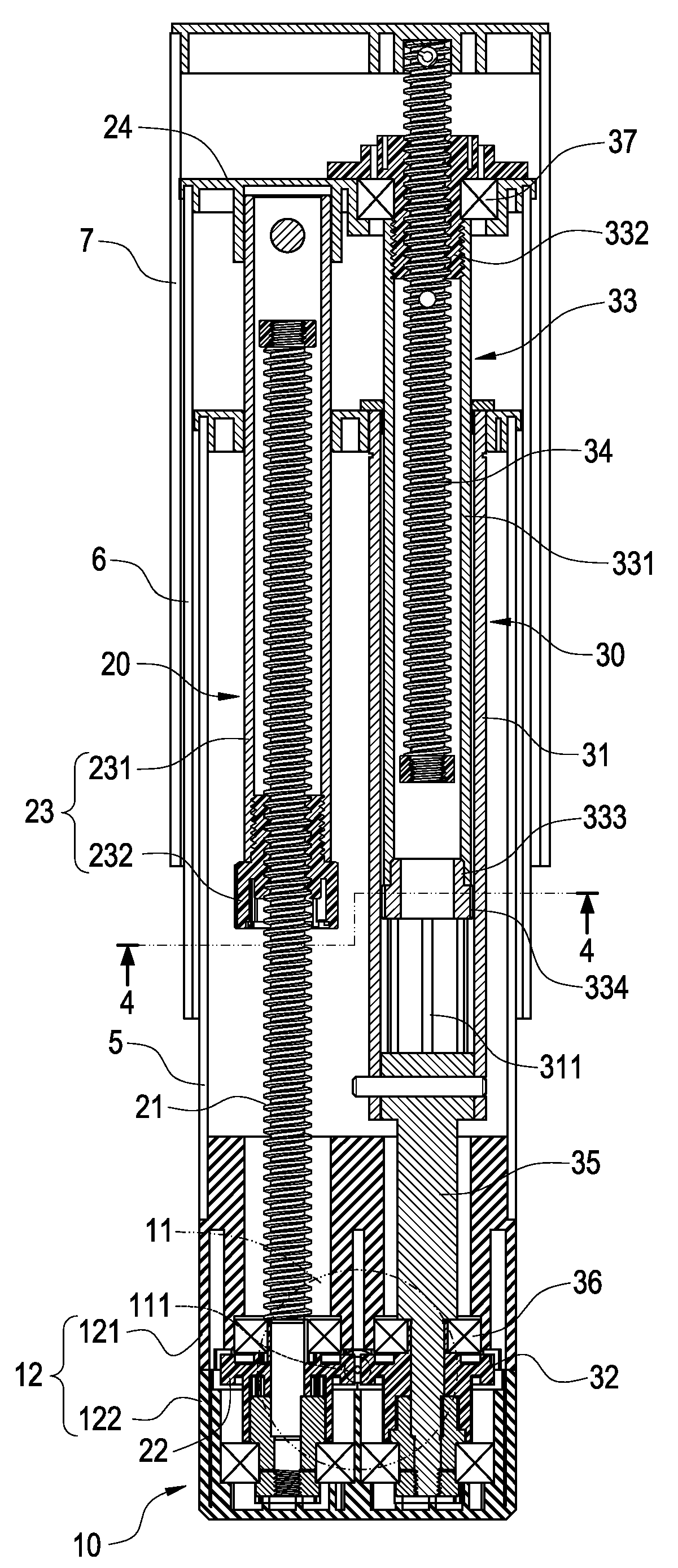
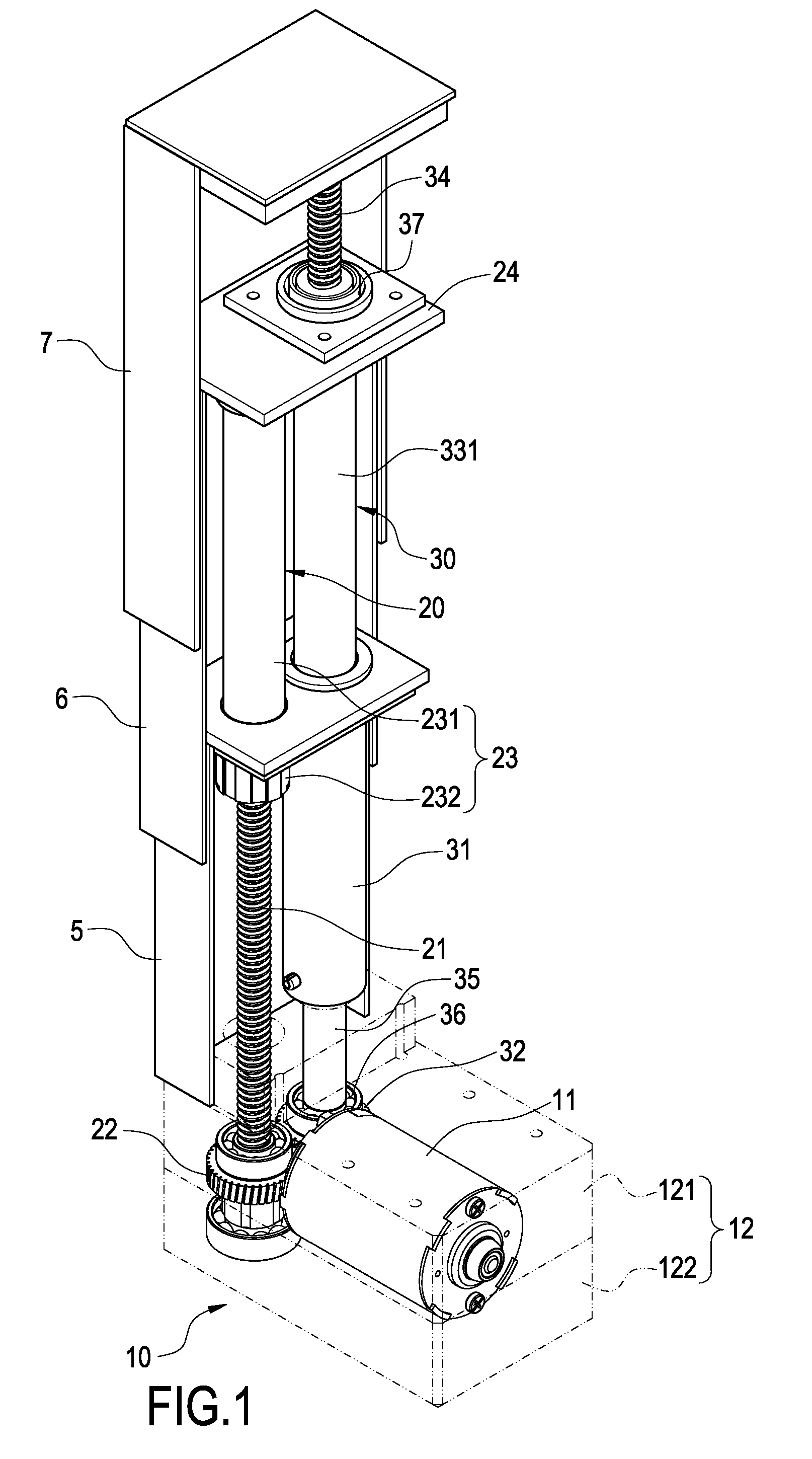
[0025]With reference to FIG. 5, it is a cross-sectional view showing the using state of the present invention. The lifting device of the present invention can be mounted on an electric table or an electric bed. In use, the rotation of the transmission shaft 111 of the motor 11 simultaneously drives the screw rod 21 of the first transmission means 20 and the connecting rod 35 of the second transmission means 20 to rotate. The screw rod 21 can make the telescopic tube assembly 23 threadedly connected to the screw rod to linearly protrude, so that the connecting piece 24 fixedly connected to the distal end of the telescopic tube 231 and the second sliding unit 6 can protrude relative to the first sliding unit 5. Further, the connecting rod 35 drives the sleeve 31 of the second transmission means 30 to rotate. With the guiding engagement between each guiding groove 311 of the sleeve 31 and each guiding rail 334 of the positioning plug 333, the telescopic tube assembly 33 can axially mov...

second embodiment

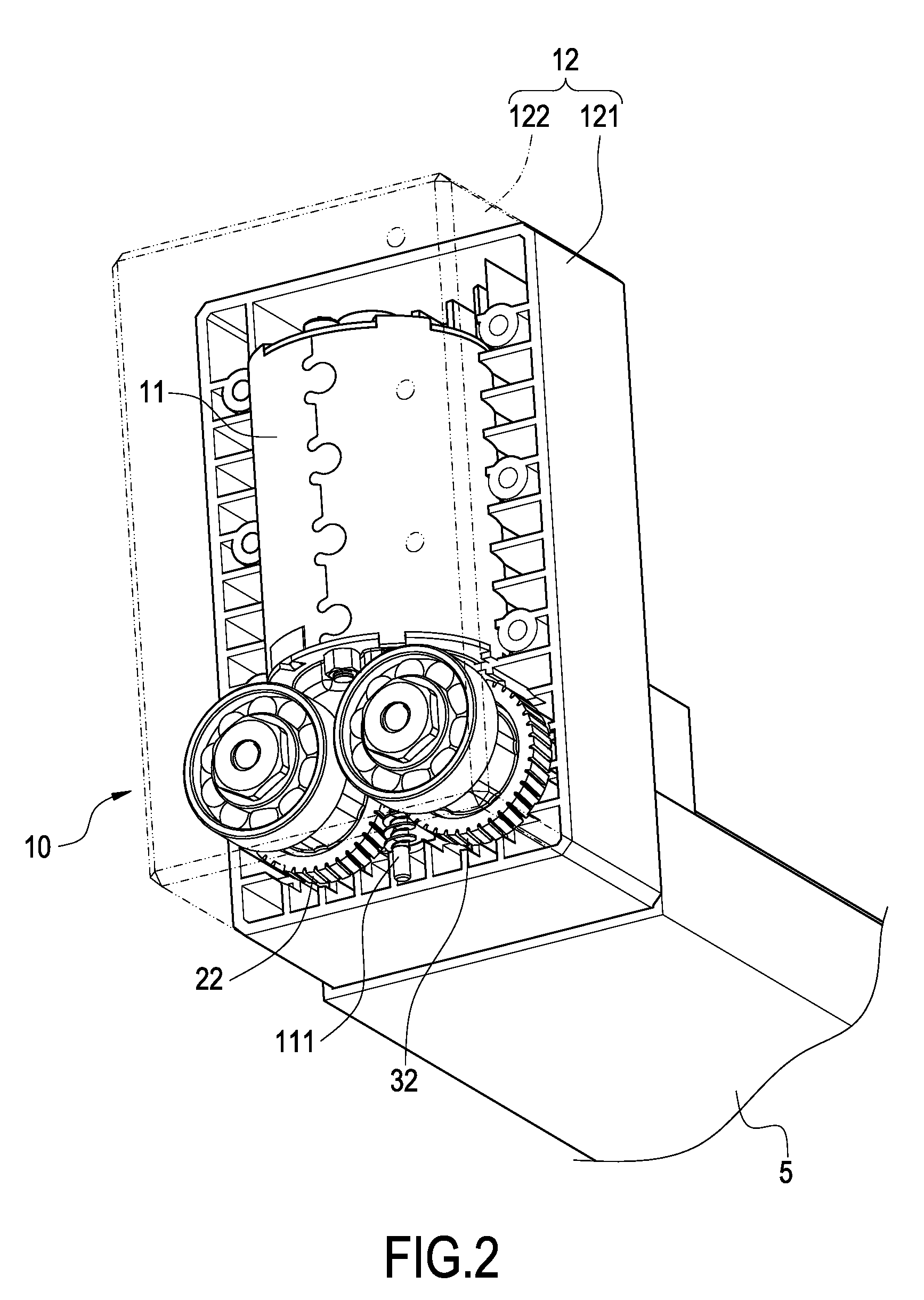
[0026]With reference to FIGS. 6 and 7, the present invention is shown. In addition to the aspect shown in the above embodiment, the driving means 10 of the present invention can has the motor 11 fixedly connected to one side of the base body 12 and the transmission shaft 111 penetrating into the base body 12 so as to drive the screw rod 21 of the first transmission means 20 to rotate. The screw rod 21 also drives the first gear 22 fixedly connected to its one end to rotate. Further, the first gear 22 and the second gear 32 of the second transmission means 30 engage with each other. A protruding shaft 321 extends outwardly from the bottom of the second gear 32. The protruding shaft 321 is fixed on the base body 12 of the driving means 10 via the lower bearing 36, so that the first gear 22 can simultaneously drive the sleeve 31 of the second transmission means 30 to rotate. As a result, the lifting device can be partially changed according to the requirements of various products so as...

third embodiment

[0027]With reference to FIG. 8, it shows the present invention. In addition to the aspect of the above embodiment, the transmission between the first transmission means 20 and the second transmission means 30 of the present invention can be achieved by the driving of a belt 25 between the first gear 22 of the first transmission means 20 and the second gear 32 of the second transmission means 30, thereby to reduce the unfavorable noise.


PUM


Abstract

A lifting device having parallel double screw rods includes a motor, a first transmission and a second transmission. The first transmission includes a screw rod driven by the motor and a telescopic tube assembly threadedly connected to the screw rod and linearly movable relative to the screw rod. The distal end of the telescopic tube assembly is fixedly connected on a connecting piece. The second transmission is provided at one side of the first transmission and parallel thereto. Further, the second transmission includes a sleeve driven by the motor to rotate, a telescopic tube assembly accommodated within the sleeve and axially movable relative to the sleeve, and a screw rod threadedly connected to the telescopic tube assembly and linearly movable relative to the telescopic tube assembly. The distal end of the telescopic tube assembly is connected to the connecting piece. With the above arrangement, each screw rod is interchangeable and the cost can be reduced.

Description

BACKGROUND OF THE INVENTION[0001]1. Field of the Invention[0002]The present invention relates to a lifting device having parallel double screw rods, and in particular to a lifting device mounted in the electric table or electric bed.[0003]2. Description of Prior Art[0004]Conventionally, a lifting device is provided within a two-stage sliding unit and then connected to an electric table or electric bed, so that the higher or lower position of the electric table or electric bed can be adjusted. Since the total length of the extension of the lifting device does not exceed the sum of two sliding units and the total length of the retraction is not lower than the length of any one longer sliding unit, the extension and retraction stroke that is possibly achieved is limited and thus cannot satisfy the requirement for a larger adjusting space in the existing market. Therefore, there is proposed a multiple-stage (such as three-stage or four-stage) sliding unit. In addition to have a larger a...

Claims


Application Information

Patent Timeline
Patent Type & Authority Patents(United States)
IPC IPC(8): F16H3/06
CPCF16H25/20F16H2025/2059Y10T74/18672F16H25/2056Y10T74/18576F16H2025/2084
Inventor WANG, CHIA-JUNG
Owner TIMOTION TECH CO LTD
Why Eureka
Try Eureka