
Deceleration device

a technology of deceleration device and cylinder, which is applied in the direction of recording information storage, transportation and packaging, instruments, etc., can solve the problems of door as well as the adjacent seat being damaged, and affecting the stability of the instrumen

Active Publication Date: 2010-05-11
AIRBUS OPERATIONS GMBH
View PDF19 Cites 3 Cited by
  • Summary
  • Abstract
  • Description
  • Claims
  • Application Information

AI Technical Summary

Benefits of technology

The present invention relates to a deceleration device for a cockpit door in the event of a cockpit decompression. The device is designed to gradually reduce the energy of the cockpit door to prevent damage to the occupants. It includes a spool reel and elevating spindle, with a collet and spring assembly to absorb the kinetic energy of the door. The device can be symmetrically and redundantly designed, and may include energy-absorbing tubes and wave spring washers to further dissipate kinetic energy. The technical effect of the invention is to provide a reliable and effective means to protect cockpit occupants in the event of a cockpit decompression.

Problems solved by technology

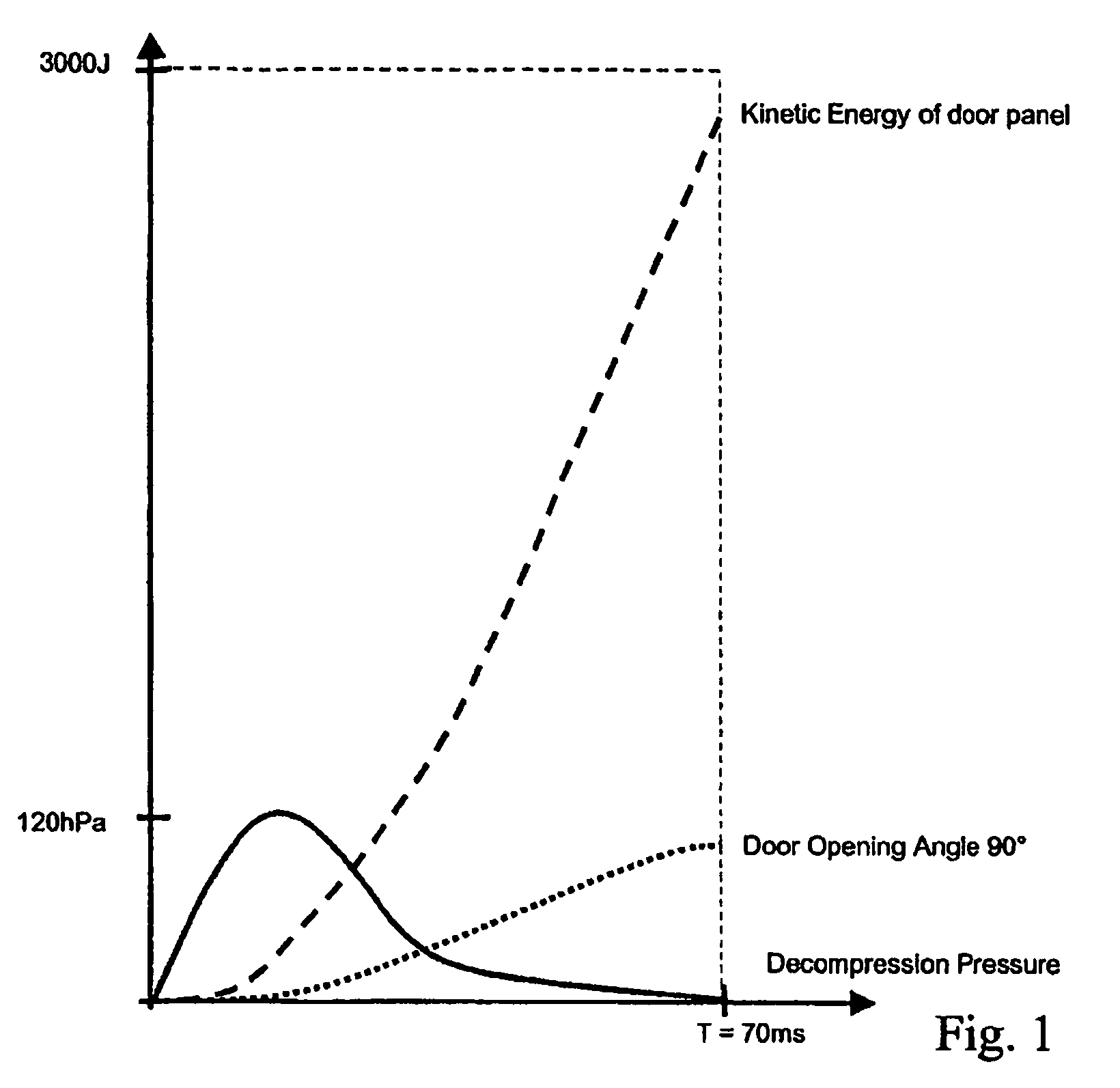
Delay of the door to provide adequate venting may result in catastrophic structural failure.
Otherwise, without an effective means of energy dissipation, the door, once it has passed 90 degrees, will collide with the seat causing potential injury to occupant and possible detachment of the seat and / or detach the door from its hinges, causing unacceptable structural / equipment damage and possible crew injury.
In this case, the resultant equivalent static reaction load applied at the centre of area of the door would be in excess of 4500 daN (4.500 kg), whereby the door as well as the adjacent seat might be damaged.

Method used


Image

  • Deceleration device
  • Deceleration device
  • Deceleration device

Examples


Embodiment Construction

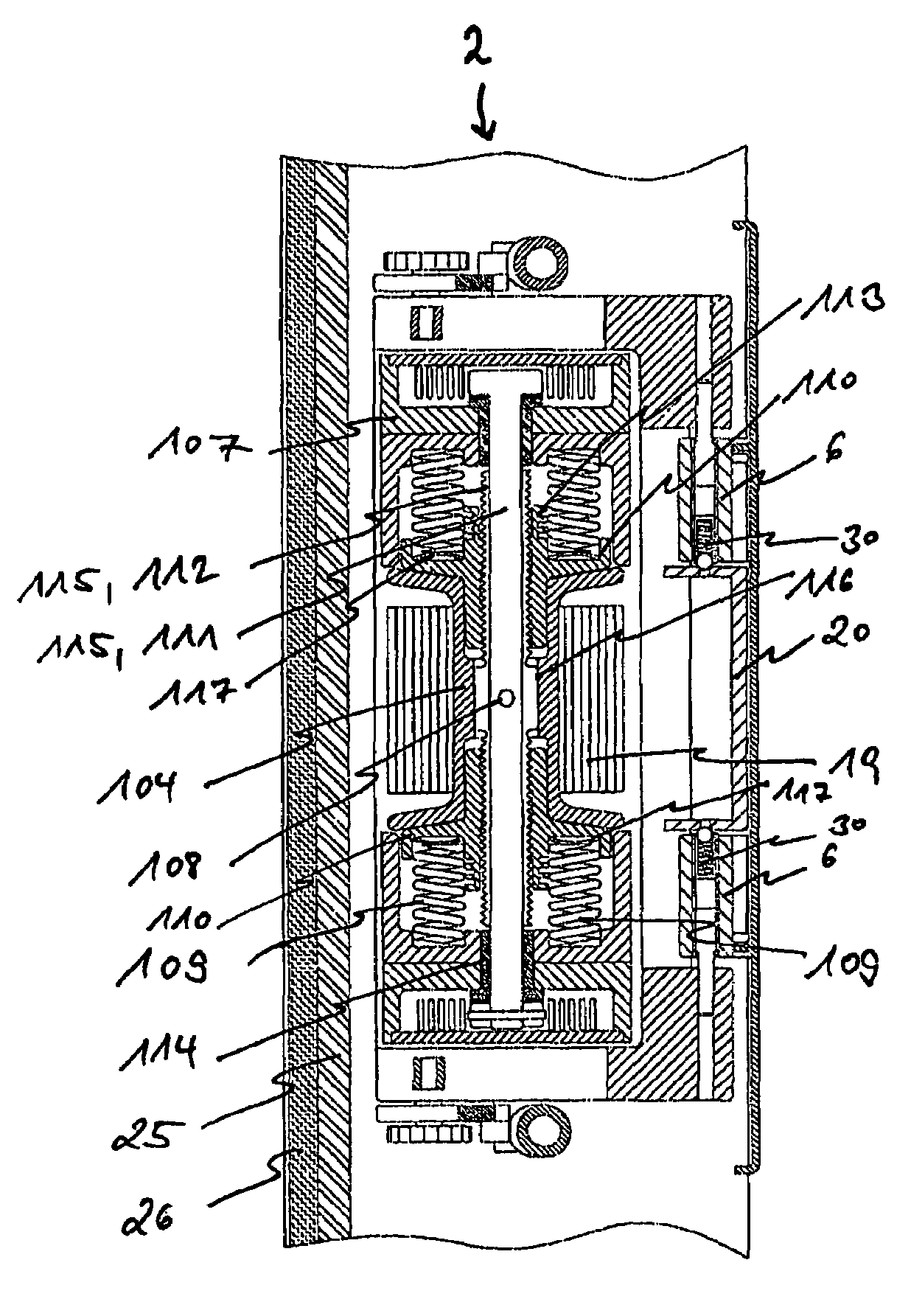
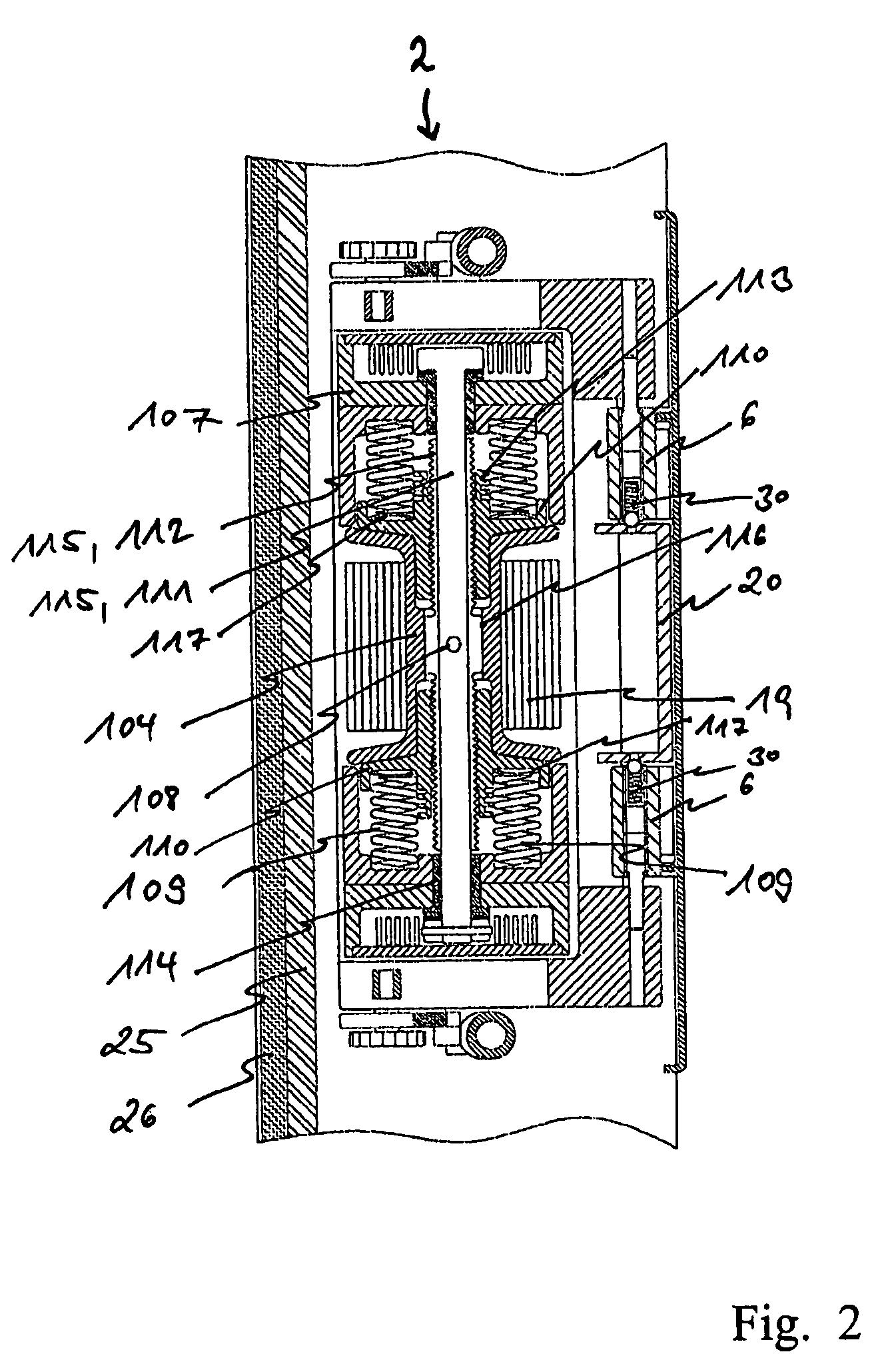
[0032]The following paragraphs detail the deceleration device 2, which is mounted within doorpost 26. As will become apparent from FIG. 2, the deceleration device 2 comprises a housing in which the main components of the device 2 are installed. In particular, an elevating spindle 115 extends in a vertical direction and rotates in two bearings 114 which are supported on housing 107. The elevating spindle 115 may consist of two mating parts, a bearing shaft 111 and a shaft sleeve 112 featuring both right hand and left hand threads either side of a short central plain shank 116.

[0033]The deceleration device 2 moreover comprises a spool reel 104 which surrounds the plain shank 116 of the elevating spindle 115. A belt 19 is wound up on the spool reel 104 and is connected to a buckle 20 which is positively held in position by means of two ball catches. The shaft assembly 111, 112 slides into the spool reel 104 and is locked to the spool reel 104 by means of a single shear pin 108. At eith...


PUM


Abstract

A deceleration device adapted for gradual dissipation of kinetic energy comprises a spool reel carrying a belt being wound up on the spool reel; an elevating spindle being driven by the spool reel when the belt is being retracted from the spool reel; at least one collet screwed to the elevating spindle; and at least one spring assembly being installed between the collet and a fixed bearing portion of the deceleration device. The at least one collet is screwed towards the fixed bearing portion by retraction of the belt from the spool reel thereby compressing the spring assembly, whereby a reaction load is generated by the spring assembly counteracting the retraction of the belt.

Description

CROSS-REFERENCE TO RELATED APPLICATIONS[0001]This application claims the benefit of the filing date of U.S. Provisional Patent Application No. 60 / 780,490 filed Mar. 8, 2006, the disclosure of which is hereby incorporated herein by reference.BACKGROUND OF THE INVENTION[0002]The present invention relates to dissipation of energy. In particular, the present invention relates to a deceleration device which is adapted to gradually dissipate kinetic energy. Moreover, the present invention relates to a cockpit door which is adapted to be connected to the deceleration device as well as to an aircraft being provided with a cockpit door comprising the deceleration device of the present invention.[0003]The cockpit door aboard an aircraft provides the primary means of dissipating pressure from the cabin to the cockpit during a cockpit decompression case. A cockpit decompression case may occur as a minimal opening involving relatively slow bleed of pressure up to a maximum opening (as defined by...

Claims


Application Information

Patent Timeline
Patent Type & Authority Patents(United States)
IPC IPC(8): B64C1/14
CPCB64C1/1469B64D45/0015B64C2001/009B64D45/0028
Inventor FRENCH, CLIVE
Owner AIRBUS OPERATIONS GMBH
Learn More