Connector assembly

a technology of connectors and assemblies, applied in the direction of coupling device connections, lighting and heating apparatus, instruments, etc., can solve the problems of affecting reliability and efficiency, adversely affecting signal transmission, and increasing emi issues, so as to improve the reliability of the connector assembly

Inactive Publication Date: 2010-05-11
DELTA ELECTRONICS INC
View PDF3 Cites 24 Cited by
  • Summary
  • Abstract
  • Description
  • Claims
  • Application Information

AI Technical Summary

Benefits of technology

[0007]To eliminate the disadvantages of the conventional connectors, the present invention provides a connector assembly including light emitting elements and light pipes. A shield having barrel-like shaped structures prevents light scattering and EMI from the light emitting elements so that the reliability of the connector assembly is improved.

Problems solved by technology

However, the PCB not only occupy considerable space, but also generate electromagnetic interference (EMI), which interferes with signal transmission.
Since the LED 11 is disposed inside the connector 1, EMI and noise may occur between the LED 11 and other interior components, such as choices or transformers, adversely affecting reliability and efficiency thereof.
As operational speed of the connectors increase, for example, from 10 Mbps to as fast as 1 Gbps, EMI issues also increase and can become a very serious problem.

Method used


Image

  • Connector assembly
  • Connector assembly
  • Connector assembly

Examples


Embodiment Construction

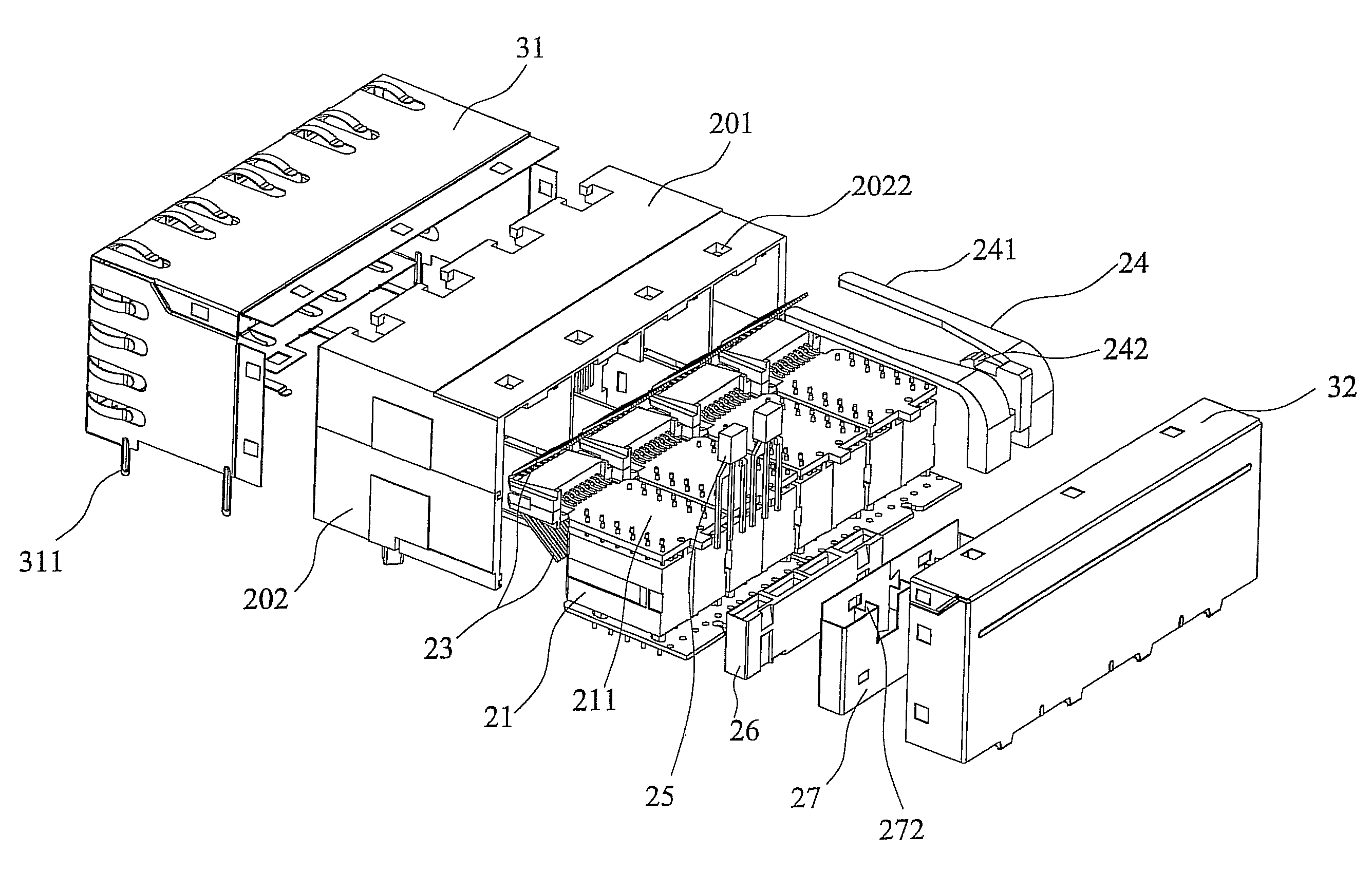
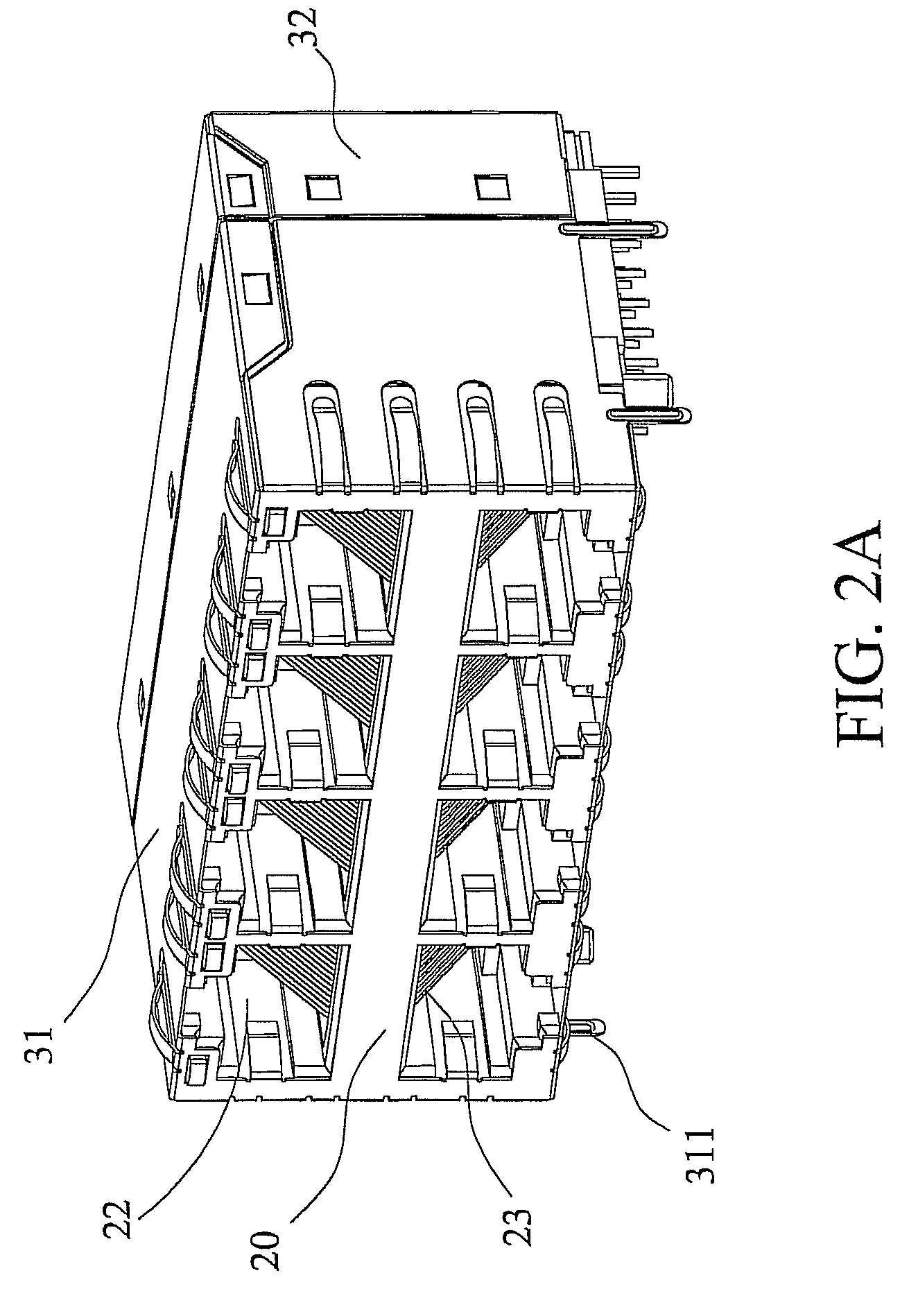
[0025]Referring to FIGS. 2A-2D, an embodiment of a connector assembly 2 according to the present invention, such as an RJ-45 connector, includes a housing 20, an electronic device 21, and a cover. As shown in FIG. 2C, the housing 20 includes a first casing 201 and a second casing 202. The first and second casings201, 202 can be connected to each other by engaging, adhering or fastening. Furthermore, the first and second casings 201, 202 can be integrally formed as a monolithic piece by injection molding. As shown in FIG. 2A, the housing 20 forms two rows of sockets 22 aligned with each other.

[0026]The electronic device 21 is disposed in the housing 20 and includes a plurality of pins 23 received in a plurality of recesses of the housing 20, correspondingly. When inserting an external plug into the sockets 22, the external plug electrically connects to the pins 23.

[0027]The electronic device 21 further includes a plurality of circuit boards 211 horizontally disposed between the first...


PUM


Abstract

A connector assembly is provided. The connector assembly includes a housing having at least a socket, an electronic device disposed in the housing, a protection member disposed on a side of the housing, a light emitting element disposed on the protection member, a light pipe disposed on the housing for guiding light from the light emitting element, a shield surrounding the protection member and the light emitting element, and a cover encompassing the light pipe, the shield, and the light emitting element.

Description

CROSS REFERENCE TO RELATED APPLICATIONS[0001]This Non-provisional application claims priority under 35 U.S.C. §119(a) on Patent Application No(s). 096143392 filed in Taiwan, Republic of China on Nov. 16, 2007, the entire contents of which are hereby incorporated by reference.BACKGROUND OF THE INVENTION[0002]1. Field of the Invention[0003]The invention relates to a connector assembly and in particular to a connector assembly having light emitting elements and light pipes.[0004]2. Description of the Related Art[0005]The conventional connector usually includes several interior components such as chokes, filters, resisters, capacitors, transformers, and light-emitting diodes (LEDs) for providing specific functions. The interior components are assembled and arranged according to electronic specifications and functional requirements, wherein at least one printed circuit board (PCB) can be provided for electrical connection between the interior components. However, the PCB not only occupy ...

Claims


Application Information

Patent Timeline
Patent Type & Authority Patents(United States)
IPC IPC(8): F21V33/00
CPCG02B6/0008H01R13/65802H01R13/7175H01R13/6658H01R13/50H01R24/64H01R13/6471H01R13/6582
Inventor TAI, YU-YUANCHEN, CHEN-JUNGCAO, JIAN-PINGZHANG, ZHONG-MINGBAI, BO
Owner DELTA ELECTRONICS INC
Why Eureka
Try Eureka