Method and device for positioning ends of pipe sections relative to one another

a technology of pipe sections and ends, applied in the direction of pipe laying and repair, auxilary devices, application, etc., can solve the problems of high operational costs of pipe laying vessels, high time costs, and inability to achieve optimal connection between pipelines and pipes, etc., and achieve the effect of less tim

Inactive Publication Date: 2010-05-11
HEEREMA MARINE CONTRACTORS NEDERLAND SE
View PDF11 Cites 20 Cited by
  • Summary
  • Abstract
  • Description
  • Claims
  • Application Information

AI Technical Summary

Benefits of technology

[0018]It is another object of the present invention to provide a method and device for positioning an end of a first pipe section relative to an end of a second pipe section wherein a better positioning of the end of the first pipe section relative to the end of the second pipe section is obtained, resulting in a smoother transition of the wall of the resulting pipeline at the connection.
[0094]In an aspect of the invention, the target position determining means is coupled via coupling means to the output organ. This provides the advantage that the measured point positions can be automatically transmitted to the target position determining means.

Problems solved by technology

However, in pipe-laying operations at sea, time is expensive.
This is due to the high operational costs of the pipe-laying vessel, and also due to the substantial number of highly skilled persons required on board the pipe-laying vessel in order to perform pipe-laying operations.
Therefore, the present method has a disadvantage in that it is very expensive.
The present method has a further disadvantage in that it is difficult to determine a substantially complete view of the dimensional variations of the pipe section and the pipeline, which may result in a non-optimum connection between the pipeline and the pipe section.

Method used


Image

  • Method and device for positioning ends of pipe sections relative to one another
  • Method and device for positioning ends of pipe sections relative to one another
  • Method and device for positioning ends of pipe sections relative to one another

Examples


Embodiment Construction

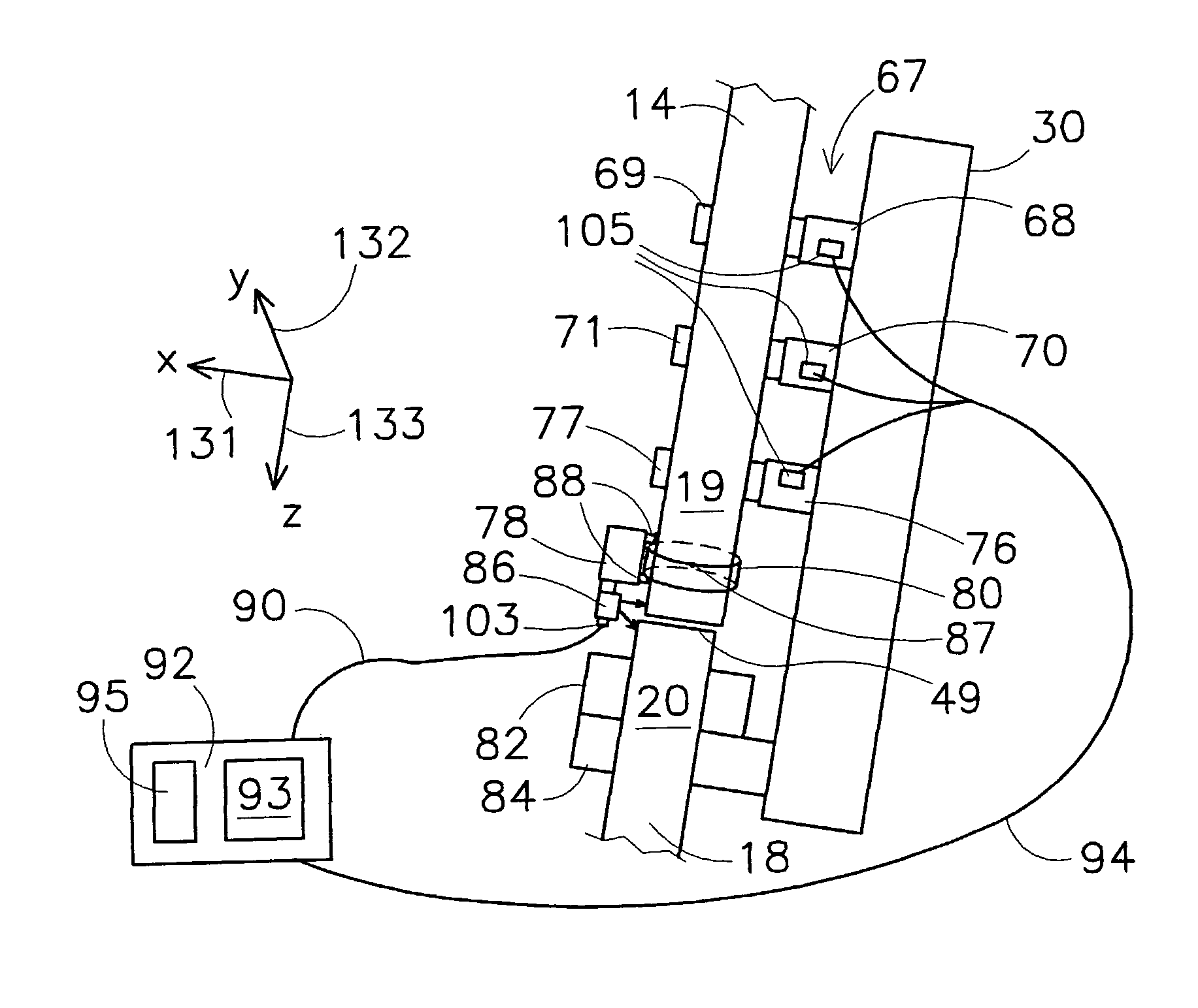
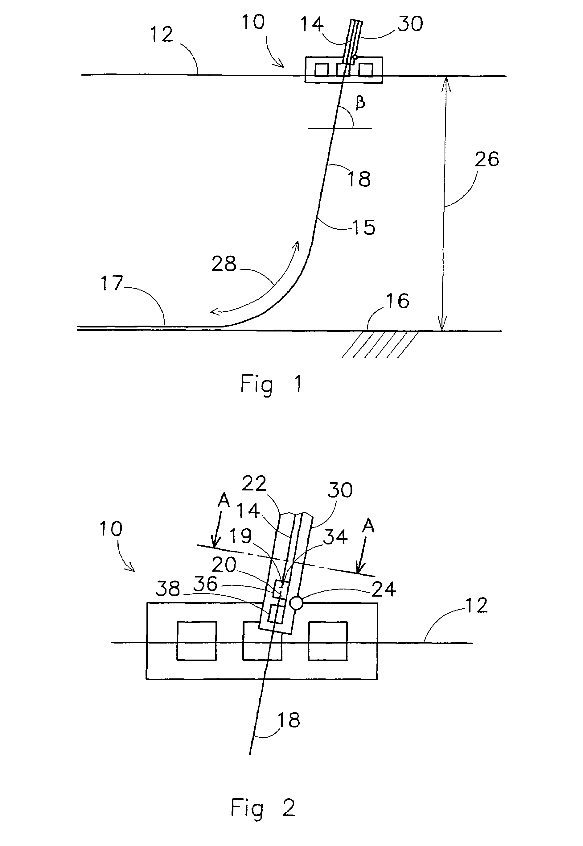
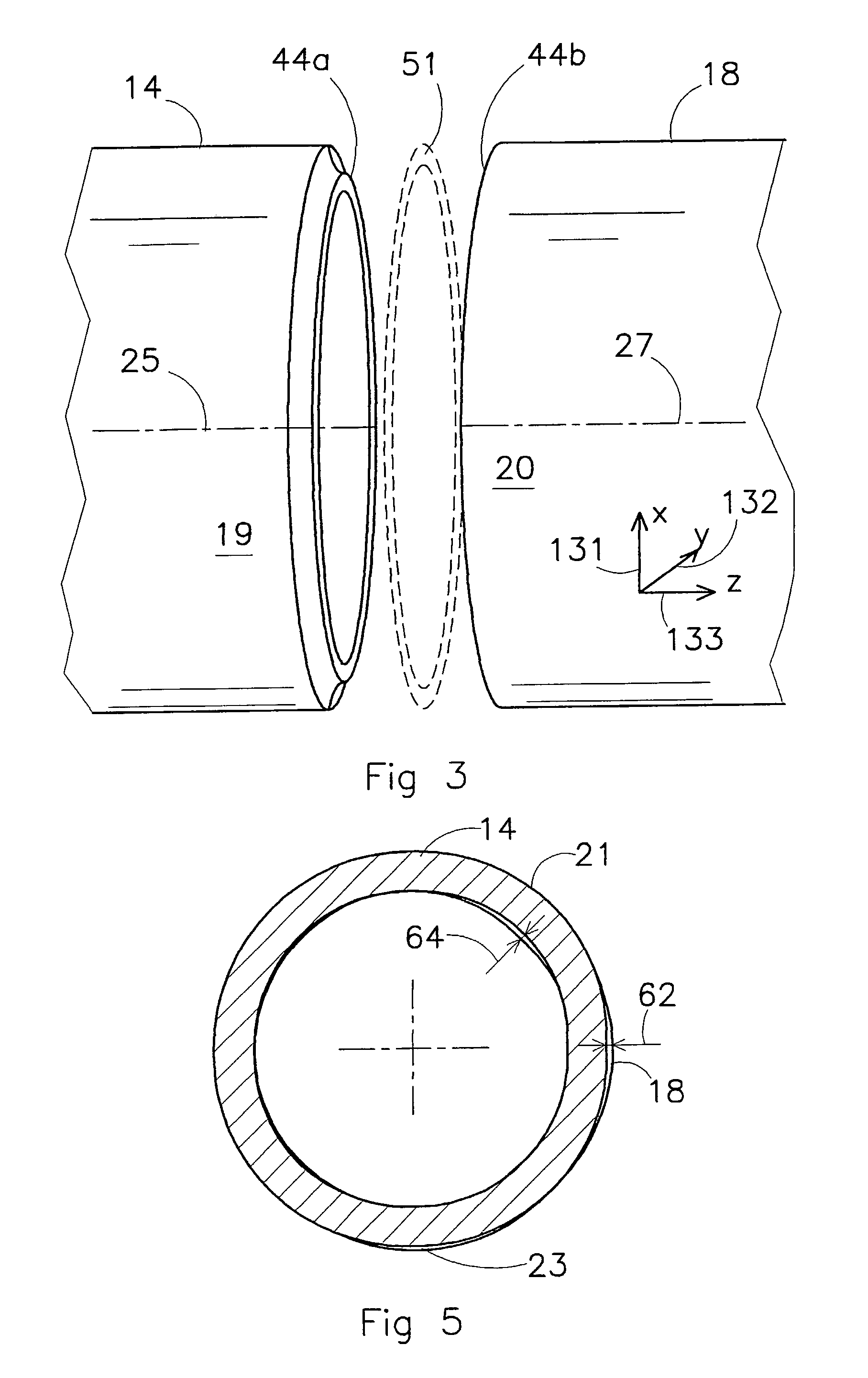
[0121]Referring to FIGS. 1 and 2, a pipe-laying vessel 10 is shown, which floats on a water surface 12. The pipe-laying vessel 10 comprises an inclined J-lay tower 30 which is connected by at least one hinge 24 to the pipe-laying vessel 10. The pipeline 18 is constructed by repeatedly welding pipe sections 14 to a free end 20 of the pipeline 18.

[0122]Depending on the water depth 26 and the submerged weight and stiffness of the pipeline 18, the tower 30 is set to an angle β with the horizontal, the angle β varying between 50 and 90 degrees.

[0123]During a J-lay operation, the pipeline 18 leaves the pipe-laying vessel 10 and extends in a J-shape between the pipe-laying vessel 10 and a seabed 16. A horizontal force is exerted on the free end 20 of the pipeline 18 by pipe-laying vessel 10 in order to prevent buckling of the pipeline 18 in the curved section 28 of the pipeline 18.

[0124]The process of adding a pipe section 14 to the pipeline 18 comprises a number of activities. First, the ...


PUM

PropertyMeasurementUnit
widthaaaaaaaaaa
widthaaaaaaaaaa
thicknessesaaaaaaaaaa

Abstract

The invention relates to a method for positioning an end (19) of a first pipe section (14) relative to an end (20) of a second pipe section (18), the method comprising: (a) prepositioning the end (19) of the first pipe section (14) near the end (20) of the second pipe section (18), defining a connection area (51) comprising the respective ends (19, 20) of the first and second pipe sections (14, 18); (b) performing a measuring process comprising a plurality of measuring steps, each measuring step comprising: (b1) moving a sensing device (86) to a location (89a, 89b, 89c) near the connection area (51); (b2) automatically measuring the location (89a, 89b, 89c) of the sensing device (86) relative to a reference location (87); (b3) automatically measuring point positions (98a, 98b, 98c, 98d) of points on the ends (19, 20) of the first and second pipe sections (14, 18) relative to the sensing device location (89a, 89b, 89c); (c) determining a target position of the end (19) of the first pipe section (14) relative to the end 20) of the second pipe section (18) on the basis of the measured point positions (98a, 98b, 98c, 98d); and (d) moving at least one of the first and second pipe sections (14, 18) in order to obtain the target position.

Description

CROSS-REFERENCE TO RELATED APPLICATIONS[0001]This application is the National Stage of International Application No. PCT / NL2005 / 000292, filed Apr. 20, 2005, the contents of which is incorporated by reference herein.FIELD OF THE INVENTION[0002]The present invention relates to a method and device for positioning an end of a first pipe section relative to an end of a second pipe section. Methods and device for positioning pipe sections relative to one another are known in the art. The present invention relates in particular to the positioning of a pipe section relative to a pipeline which is laid at sea.[0003]When a pipeline is constructed, pipe sections are positioned in and end-to-end relationship and connected to one another. When the pipeline is made of a metal, the pipe sections are generally welded to the pipeline.[0004]During the laying of a pipeline at sea, the pipeline is suspended by a free end thereof from a pipe-laying vessel. The pipeline extends from the pipe-laying vesse...

Claims


Application Information

Patent Timeline
Patent Type & Authority Patents(United States)
IPC IPC(8): B23K9/00F16L1/235
CPCB23K37/0533G01B21/24B23K2201/06B23K2101/06
Inventor VERKUIJL, ALEXANDER LAMBERTUS JOHANNESDE GOEDE, PIETERADRIAANSEN, JOHANNES HENDRIKVAN ZANDWIJK, CORNELIS
Owner HEEREMA MARINE CONTRACTORS NEDERLAND SE
Why Eureka
Try Eureka