Dental mirror, and an intraoral camera system using the same

a camera system and mirror technology, applied in the field of dental mirrors and intraoral camera systems, can solve the problems of mirror or the surface of the camera lens fogging up, the dentist has no way of knowing that the patient is accurately viewing the target projected by the hand mirror, and the situation is worse, so as to enhance the field of view

Inactive Publication Date: 2010-05-11
TAKAHASHI ATSUSHI
View PDF19 Cites 17 Cited by
  • Summary
  • Abstract
  • Description
  • Claims
  • Application Information

AI Technical Summary

Benefits of technology

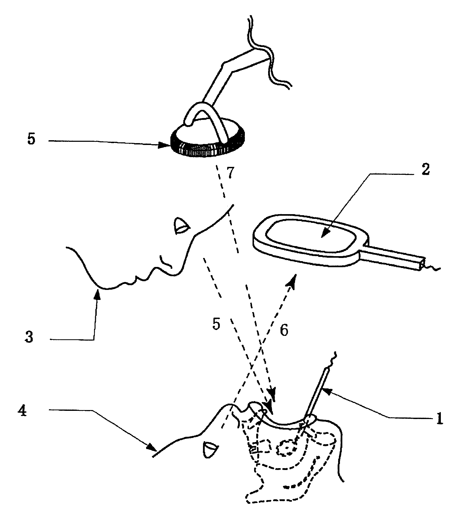
[0007]To overcome at least one of these problems, the present invention intends to provide a means to convey the image a dentist directly views to his or her patient without shifting his or her line of view from the patient when the dentist describes the condition of a disease in a problem area that the patient cannot directly see while he or she is laid on a bed for examination and treatment. The present invention also intends to provide an intraoral camera system with a defogging mirror and camera lenses.
[0008]More specifically, in an example of the present invention, reflective material is removed from a dental mirror at a center or any other area of its back surface to transmit light therethrough and a CCD camera is attached thereto. The image data received from the CCD camera is sent to a hand-mirror shaped monitor via radio or cable. In this way, even though the patient is laid horizontally on a bed for examination or treatment and is in a position where he or she is unable to see the target area, the dentist can provide the target image in the same field of view to the patient that the dentist views in a dental mirror without shifting his or her line of view from the patient's mouth. In an example of the present invention, the image is also stored in a server to make it available at any time.
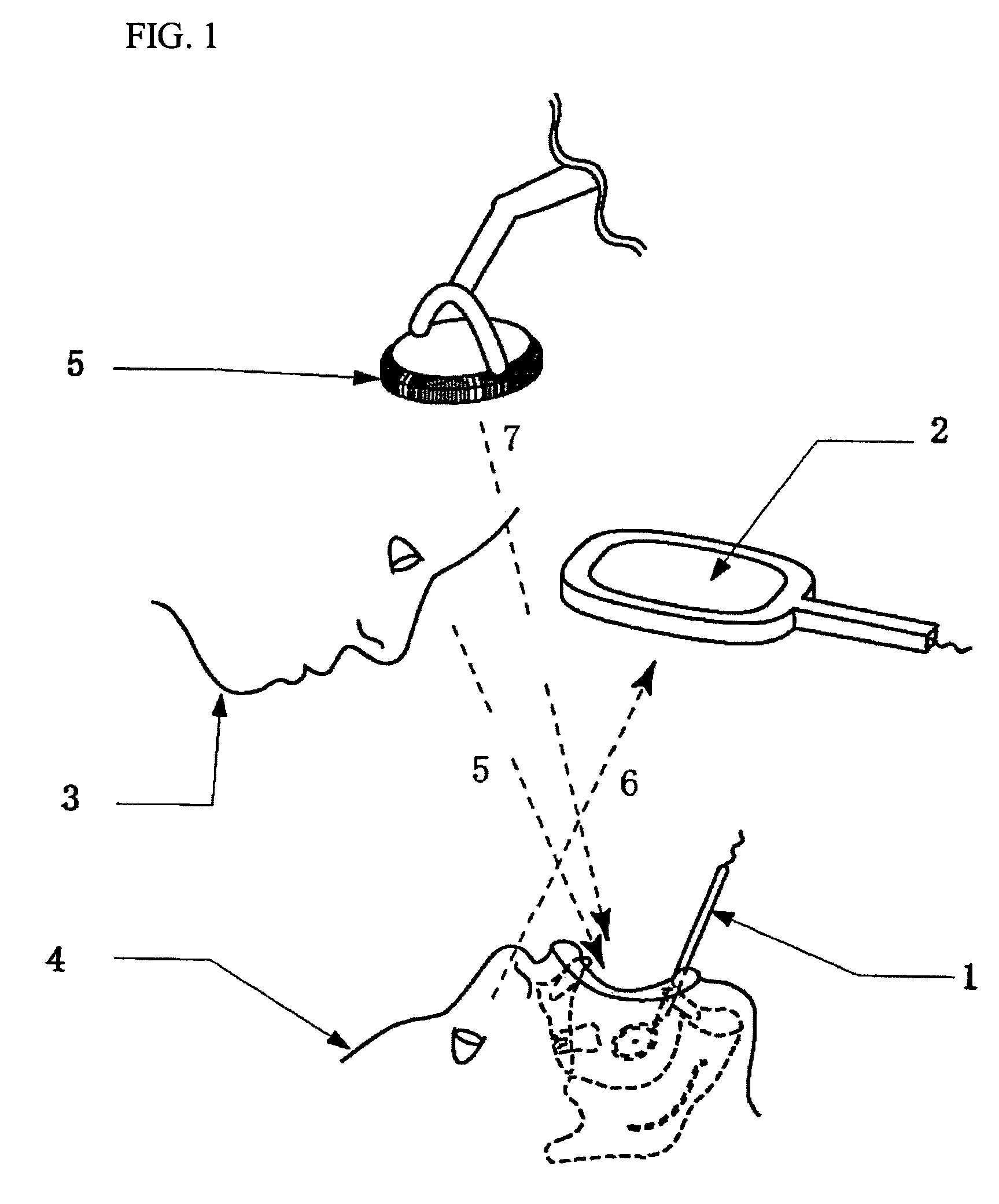
[0009]The dental mirror comprises a CCD camera attached to the center of the back surface of a dental mirror, a gear attached to the same rotary shaft as that of the CCD camera such that the gear rotates around the CCD camera, a battery driven micromotor, a battery positioned inside the dental mirror holder, a gyro sensor for outputting a signal that incorporates a motion of the gyro sensor with that of the gear on inclination of the dental mirror to a horizontal plane or floor, and a control mechanism for controlling the rotation angle of the CCD camera in accordance with the signal from the gyro sensor. In this way, even though the dentist continuously moves the dental mirror longitudinally or horizontally to capture images of the patient's teeth, the image of the target is captured at a preset angle, which is constant. Thus, the dentist can easily determine which teeth are on the liquid crystal screen regardless of the angle at which the dentist holds or inserts the dental mirror in the patient's mouth.
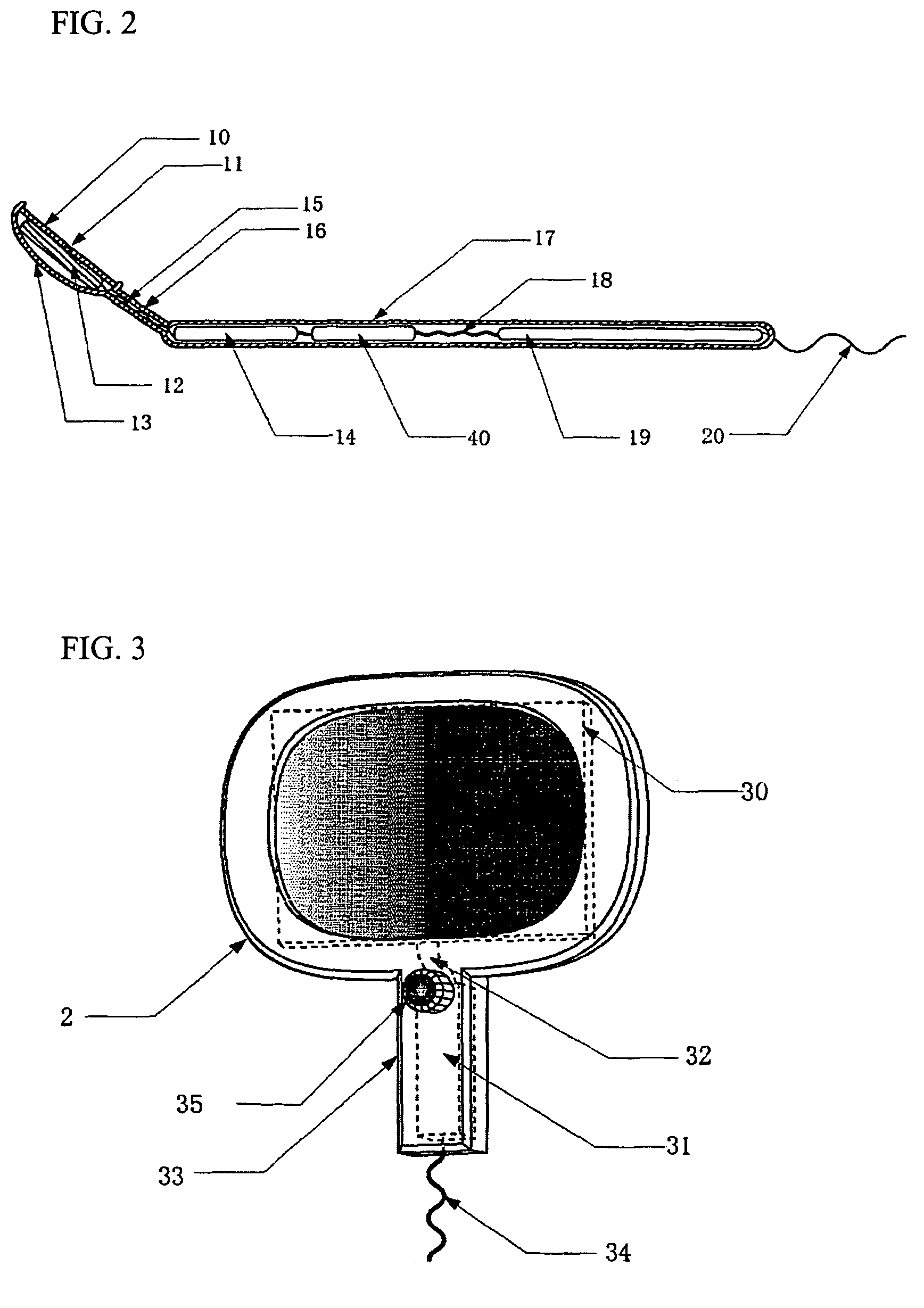
[0010]The hand mirror shaped monitor is very compact so that the patient can hold it wherever it is easy for the patient as he or she lies in a horizontal position on a bed. The monitor further comprises a liquid crystal plate having a portion at the center where some liquid crystal is removed to transmit light therethrough, and a CCD camera, which is provided on a back surface of the liquid crystal plate, which allows capturing a frontal image of the front teeth or face at the same level as the line of view through the incident portion where some liquid crystal material is removed. This configuration provides an image that is free from all directional distortion on the CCD dental mirror, which is as manageable as a regular mirror. The hand mirror shaped monitor having an image conversion processor is capable of inverting the data input from the center CCD camera in terms of backside forward and upside down or rotating clockwise or counterclockwise. It is therefore capable of reproducing on a liquid crystal screen an upright image, not the inverted image that a regular mirror produces but the same image of the face that a third party can see with his or her eyes.
[0015]Nonetheless, the camera lens surface of the intraoral camera system described above often collects moisture due to the patient's breathing or cooling water supplied to a polishing tool. To resolve this problem, an airway pipe having a jet nozzle pointing toward the CCD camera and optical fiber's incident portion, is provided coaxially with the dental mirror holder to inject air into the surface of the dental mirror, CCD camera, and optical fiber's incident portion to blow away moisture, saliva, cooling water and the like, thereby enhancing the field of view.
[0016]When the patient is uncomfortable with dryness due to air injected into his or her mouth, the opposite end of the jet nozzle may be hooked up with a suction port connected to a vacuum device to suck out the injected air. The patient's mouth can thus be protected from drying.

Problems solved by technology

When the dentist explains the condition of the problem area to his or her patient using two dental mirrors while the patient views the areas such as anterior teeth, lingual surface, posterior teeth, and occlusal surface with a hand mirror, the dentist has no way of knowing that the patient is accurately viewing the target projected by the hand mirror.
The situation is worse when one tries to project the patient's front teeth or face on a liquid crystal screen in the same manner one projects the image on a reflector.
Often, a mirror or the surface of a camera lens fogs up due to the patient's breathing or cooling water supplied to polishing tools.

Method used


Image

  • Dental mirror, and an intraoral camera system using the same
  • Dental mirror, and an intraoral camera system using the same
  • Dental mirror, and an intraoral camera system using the same

Examples


Embodiment Construction

[0026]Several examples of the present invention are described herein by incorporating the drawings. FIG. 2 is a working example of the present invention in which the same reference symbols designate the same component. In the example illustrated in FIG. 2, a CCD camera rotation unit 12 is attached to a point inside rear mirror head cover 13 attached to reflector 10 of the dental mirror and a light transmitting aperture 11 is formed in the center of reflector 10, which is the lens thereof, to capture the image of an object in front of the dental mirror. This image is converted to image data by the CCD camera board with a battery 14 provided inside body handle 17 and connected to CCD camera board connection cable 15 in shank 16 and transmitted by transmitter 19 through transmission antenna 20 via CCD camera board and transmitter connecting cable 18.

[0027]In the CCD camera 48, as illustrated in FIG. 8, a gyro sensor is attached to a point in body handle 17 and controller 40 together dr...


PUM


Abstract

An intraoral camera system is disclosed, which includes a dental mirror having a aperture for transmitting light therethrough, the aperture being provided in the center or any other part of the mirror by removing a reflective material therefrom. A CCD camera is secured on a back surface of the dental mirror in such a manner that the aperture coincides with its incident portion coincides with aperture in the dental mirror. A hand mirror shaped monitor is also provided for displaying image data received from the CCD camera via cable or radio, and a server is also provided that is capable of storing and outputting the image data any time onto the monitor, wherein even though a patient is laid down on a chair in a horizontal position, the patient or a third party can utilize the hand mirror shaped monitor to view an image which is very close to the image that a dentist views through reflection from the dental mirror having said CCD camera built therein.

Description

TECHNICAL FIELD[0001]The present invention relates to a technology that assists doctors or dentists to obtain informed consent from their patients by providing a visual aid that allows patients to view, regardless of their body position, the area in the patients' mouth which the patients' cannot see with only a single reflector.RELATED ART[0002]Generally, when a dentist or doctor discusses the situation of a problem area which his or her patient cannot directly see, the dentist or doctor uses two reflectors or otherwise uses a liquid crystal or CRT monitor along with an input device such as a CCD.[0003]Nonetheless, as described above, a dentist or doctor examines and treats the patient who is in a horizontal position laid in a bed. When the dentist explains the condition of the problem area to his or her patient using two dental mirrors while the patient views the areas such as anterior teeth, lingual surface, posterior teeth, and occlusal surface with a hand mirror, the dentist has...

Claims


Application Information

Patent Timeline
Patent Type & Authority Patents(United States)
IPC IPC(8): A61C1/00H04N7/18A61B1/247
CPCA61B1/05A61B1/247A61B1/07
Inventor TAKAHASHI, ATSUSHI
Owner TAKAHASHI ATSUSHI
Why Eureka
Try Eureka