Switching regulator control circuit, switching regulator using the circuit, and switching signal generating apparatus

a switching regulator and control circuit technology, applied in the field of switching regulators, can solve the problems of erroneous operation of peripheral circuits, increased switching noise, and accordingly unstable output, and achieve the effects of reducing constant current, reducing switching noise, and shortening the on-time of second switching signals

Active Publication Date: 2010-05-11
ROHM CO LTD
View PDF14 Cites 12 Cited by
  • Summary
  • Abstract
  • Description
  • Claims
  • Application Information

AI Technical Summary

Benefits of technology

[0016]The second switching signal generating circuit may make the on-time of the second switching signal shift temporally from the on-time of the first switching signal. By shifting the on-times of the switching signals temporally, the first and second switching elements can be prevented from being turned on simultaneously.
[0017]The second switching signal generating circuit may set the predetermined target value so that the on-time of the second switching signal does not overlap the on-time of the first switching signal. By adjusting the lapse time from the rising edge of the first switching signal to the rising edge of the second switching signal, two switching signals can be prevented from being turned on simultaneously.
[0021]In the second switching signal generating circuit, the second on-time control circuit may shorten the on-time of the second switching signal when the lapse time from the rising edge of the first switching signal to the rising edge of the second switching signal is short, and increase the on-time of the second switching signal when the lapse time is long.
[0023]By changing the value of the constant current for charging the capacitor in the timer circuit, when the constant current is increased, the on-time of the second switching signal can be shortened. When the constant current is decreased, the on-time of the second switching signal can be increased.
[0024]The on-time correction circuit may decrease the constant current when the lapse time from the rising edge of the first switching signal to the rising edge of the second switching signal is short, and increase the constant current when the lapse time from the rising edge of the first switching signal to the rising edge of the second switching signal is long.

Problems solved by technology

Consequently, there is a problem that the system cannot follow a load fluctuation and a fluctuation in the input voltage higher than the switching frequency, and an output is accordingly unstable.
Further, when the input current increases instantaneously, switching noise increases.
It causes problems of erroneous operation of peripheral circuits and increase in EMI (Electro Magnetic Interference).
The problems will be considered with respect to switching regulators of two systems.
It becomes difficult to obtain synchronization of the channels, and there is the possibility that a plurality of switching signals are turned on simultaneously.
Therefore, in the case of using switching regulator of the constant on-time system in a plurality of channels, a problem of increase in the input current or EMI increases occurs.

Method used


Image

  • Switching regulator control circuit, switching regulator using the circuit, and switching signal generating apparatus
  • Switching regulator control circuit, switching regulator using the circuit, and switching signal generating apparatus
  • Switching regulator control circuit, switching regulator using the circuit, and switching signal generating apparatus

Examples


Embodiment Construction

[0040]The invention will now be described based on preferred embodiments which do not intend to limit the scope of the present invention but exemplify the invention. All of the features and the combinations thereof described in the embodiment are not necessarily essential to the invention.

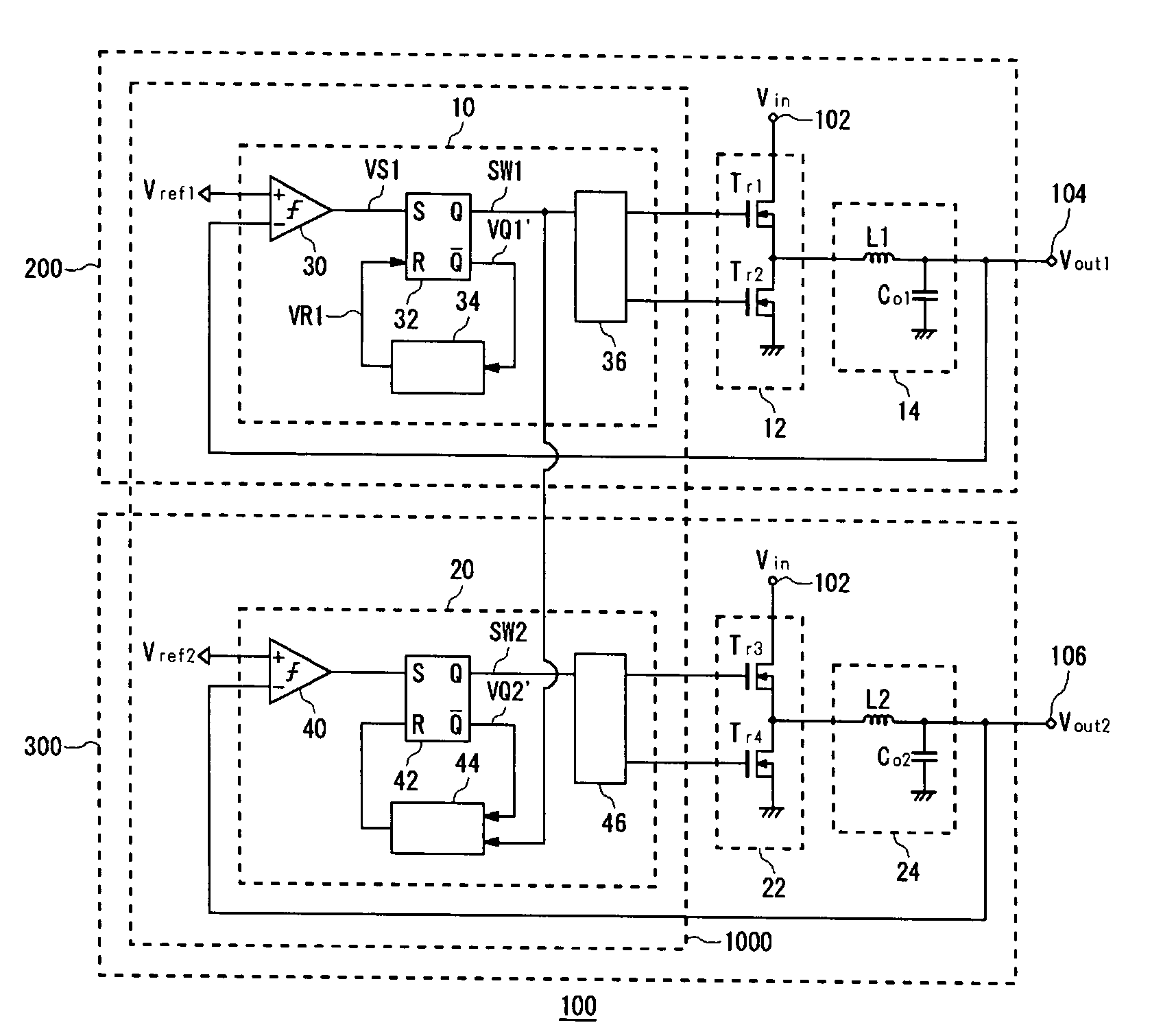
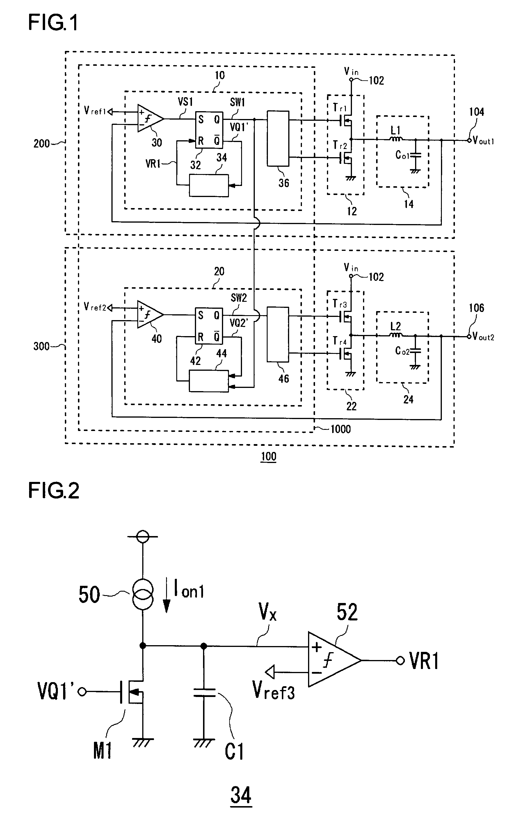
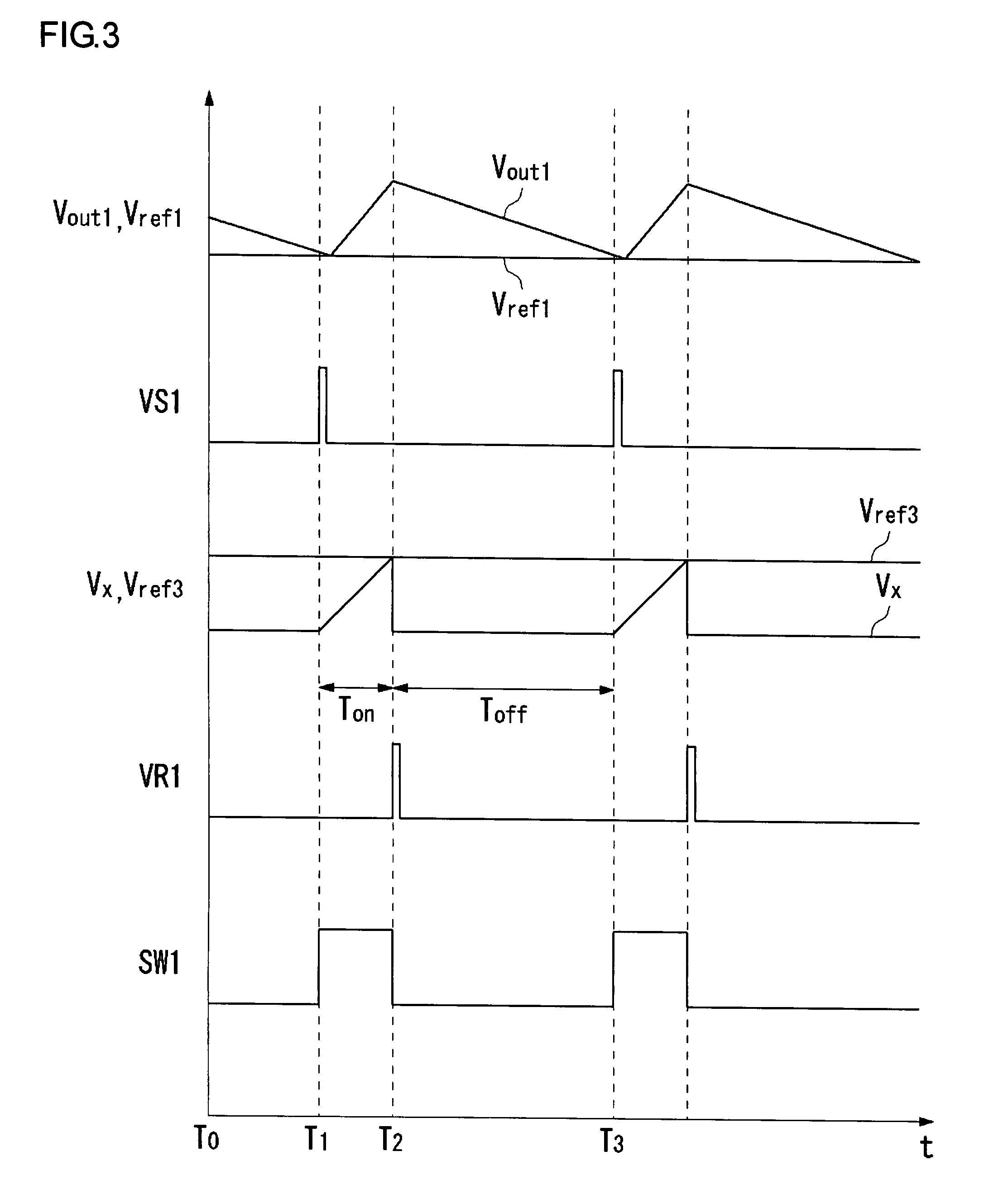
[0041]FIG. 1 shows the configuration of a switching regulator 100 according to an embodiment of the invention. In the following diagrams, the same reference numerals are designated to the same components and repetitive description will not be given. FIG. 8 is a block diagram showing the configuration of an electronic device 400 on which the switching regulator 100 of FIG. 1 is mounted. The electronic device 400 is, for example, a personal computer, a digital appliance, or a battery-powered small-sized information terminal such as a portable telephone terminal, a CD player, or a PDA. In the following embodiments, the electronic device 400 will be described as a cellular phone terminal.

[0042]The elec...


PUM


Abstract

A switching regulator includes a first switching regulator corresponding to a master channel, and a second switching regulator corresponding to a slave channel. The first switching regulator generates first output voltage Vout1 by a constant on-time system in which on-time is constant. On the other hand, the second switching regulator monitors a first switching signal and a second on-time control circuit determines on-time of a second switching signal in accordance with lapse time from the rising time of the first switching signal to the rising time of a second switching signal.

Description

CROSS REFERENCE TO RELATED APPLICATIONS[0001]This is a U.S. national stage of application No. PCT / JP2005 / 017350, filed on 21 Sep. 2005. Priority under 35 U.S.C. §119(a) and U.S.C. §365(b) is claimed from Japanese Application No. 2004-316606, filed 29 Oct. 2004, the disclosure of which is also incorporated herein by reference.BACKGROUND OF THE INVENTION[0002]1. Field of the Invention[0003]The present invention relates to a power supply apparatus and, more particularly, to a switching regulator.[0004]2. Description of the Related Art[0005]In various electronic devices, in order to supply a proper voltage to an electronic circuit internally used, a step-up-type or step-down-type DC / DC converter such as a switching regulator is widely used. Such a switching regulator has a switching regulator control circuit for generating a switching signal for controlling on / off of a switching element.[0006]As a switching signal, a PWM (Pulse Width Modulation) signal having a constant frequency for tu...

Claims


Application Information

Patent Timeline
Patent Type & Authority Patents(United States)
IPC IPC(8): G05F1/00
CPCH02M3/158
Inventor TAKEMURA, KO
Owner ROHM CO LTD
Why Eureka
Try Eureka