Fiber optic link, a transceiver for use in the link, and methods for designing and constructing fiber optic links and transceivers

a technology of optical fiber and fiber optic link, which is applied in the direction of electromagnetic transceivers, optical elements, instruments, etc., can solve the problems of high cost associated with testing the difficulty in manufacturing, and difficulty in yielding high data rate optical components of the transceiver, and achieve low relative intensity noise

Inactive Publication Date: 2010-05-11
BROADCOM INT PTE LTD
View PDF2 Cites 8 Cited by
  • Summary
  • Abstract
  • Description
  • Claims
  • Application Information

AI Technical Summary

Problems solved by technology

At high data rates such as, for example, 10 Gigabits per second (Gb / s), it is difficult to manufacture, with high yield and low cost, laser-based transceivers using the traditional design methodology.
There are many reasons for this, some of which are (1) the difficulty and precision required to ensure high quality signal paths within the transceiver, (2) the difficulty in yielding high data rate optical components of the transceiver, and (3) the high cost associated with testing the components of the transceiver.
Therefore, the length of the fiber is a limiting factor on the bandwidth of the link.
However, because low bandwidth fiber is used for these links, in order to ensure proper operation, these transceivers incorporate very complex equalizers and high bandwidth optical components, which increase the cost of the transceiver.
Although these transceivers are expected to be generally cost effective for their intended applications, they are still relatively expensive compared to lower bandwidth transceivers and are difficult to manufacture, yield and test.

Method used


Image

  • Fiber optic link, a transceiver for use in the link, and methods for designing and constructing fiber optic links and transceivers
  • Fiber optic link, a transceiver for use in the link, and methods for designing and constructing fiber optic links and transceivers
  • Fiber optic link, a transceiver for use in the link, and methods for designing and constructing fiber optic links and transceivers

Examples


Embodiment Construction

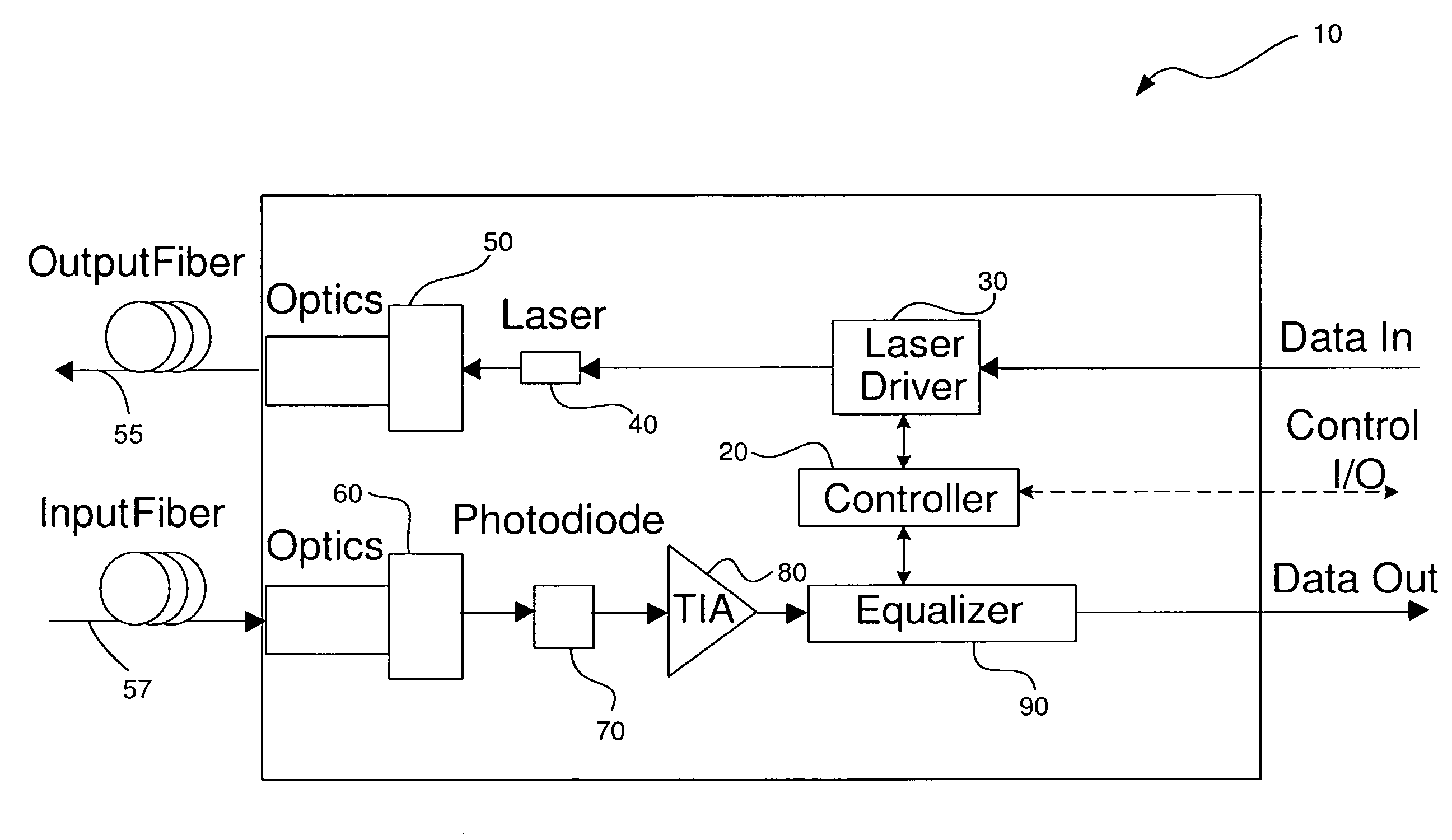
[0022]In accordance with various embodiments that will be described herein, a fiber optic link is provided that uses a relatively low-cost transceiver that incorporates relatively inexpensive low bandwidth optical and electrical components to achieve high data rate operation. In addition, the length of the optical fiber used in the link is not a limiting factor on the bandwidth of the link, although the specified optical bandwidth per unit length for a given type of fiber will be a limitation on how long the fiber of the link can be, as will be described below in detail. Furthermore, the data rate of the fiber optic link can be greater than the data rate of the laser of the transceiver provided the laser meets certain noise requirements; in particular, the relative intensity noise (RIN) of the laser must be low enough to ensure low bit error rate (BER) operation of the link. Prior to describing all of the various aspects of the various embodiments of the invention in detail, the opt...


PUM


Abstract

A fiber optic link is provided that uses a relatively low-cost transceiver that incorporates relatively inexpensive low bandwidth optical and electrical components to achieve high data rate operations. The data rate of the fiber optic link can be greater than the data rate of the laser of the transceiver provided the laser meets certain noise requirements; in particular, the relative intensity noise (RIN) of the laser must be low enough to ensure low bit error rate (BER) operation of the link.

Description

TECHNICAL FIELD OF THE INVENTION[0001]The invention relates to optical fiber links. More particularly, the invention relates to an optical fiber link having a laser-based transceiver and methods for designing such links with the capability of achieving high data rates using relatively low-cost laser-based transceivers.BACKGROUND OF THE INVENTION[0002]Traditionally, non-equalized, multimode fiber, laser-based, fiber optic links are designed with high bandwidth optical transmitters and receivers. This ensures that the dominant cause of inter-symbol interference (ISI) is the optical fiber used for connecting the transmitter and receiver, and not the receivers or transmitters. Usually, the longest link length for proper operation is then determined based on a target maximum ISI penalty. In standards-based fiber optic links, the maximum ISI penalty is usually in the range 3 to 4 optical decibels (dB).[0003]At high data rates such as, for example, 10 Gigabits per second (Gb / s), it is diff...

Claims


Application Information

Patent Timeline
Patent Type & Authority Patents(United States)
IPC IPC(8): G02B6/28H04B10/43
CPCH04B10/6971
Inventor CUNNINGHAM, DAVID GEORGEKANESHIRO, RONALDABOULHOUDA, SAMIR
Owner BROADCOM INT PTE LTD
Why Eureka
Try Eureka