Method for synchronization in networks

a network and network technology, applied in the field of network synchronization, can solve the problems of time delay during the transportation of such messages, limited local time synchronization, and less accurate synchronization, and achieve the effect of outstanding quality

Active Publication Date: 2010-05-11
SMSC HLDG
View PDF28 Cites 47 Cited by
  • Summary
  • Abstract
  • Description
  • Claims
  • Application Information

AI Technical Summary

Benefits of technology

[0014]In view of this prior art, one object of the invention is to propose a method for s

Problems solved by technology

In this case, depending on the type of the network and the traffic in the network—different time delays may occur during the transportation of such messages.
This variability of the time delays during transportation of messages restricts the possible synchronization of the local time at the various nodes, however.
However, this method generally requires two or more reference nodes, and with a smaller number of time messages less accurate synchronization is also achieved.
This method has the disadvantage that the various nodes have to transmit, receive and evaluate circulating messages repeatedly in order to make it possible to assess which of the time messages from the reference clock are the best ones.
Furthermore, the respective node only ever knows the total delay time of one circulating message—that is to say a message which has been transmitted by it and received again by it—and it therefore cannot state whether the message, for example, was traveling for a particularly long time on the forward path to a specific node or on the return path from this node through the network.
To this extent, the synchronization accuracy is also restricted, since only the total delay time of a circulating message is ever available as a selection criterion for synchronization of

Method used


Image

  • Method for synchronization in networks
  • Method for synchronization in networks
  • Method for synchronization in networks

Examples


Embodiment Construction

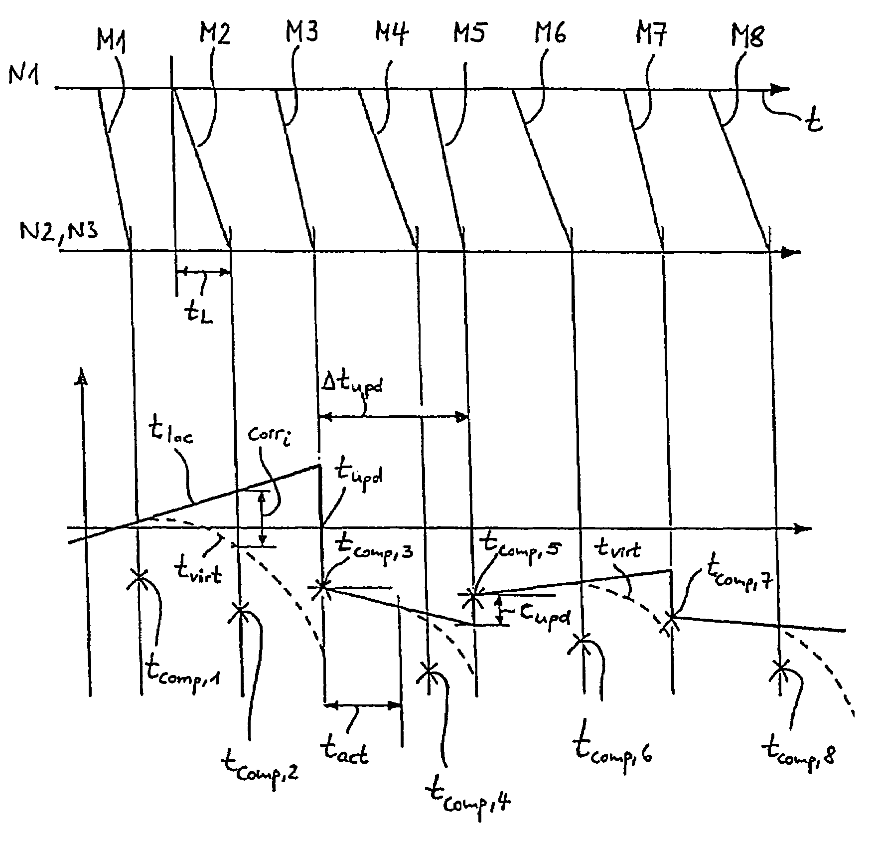
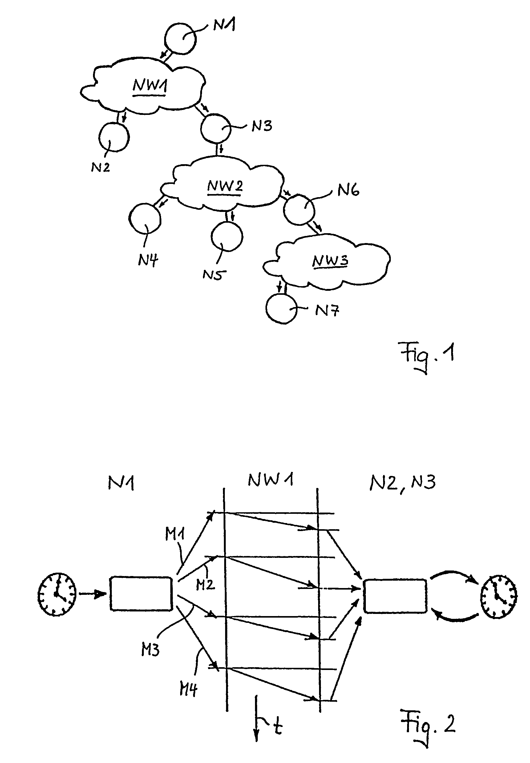
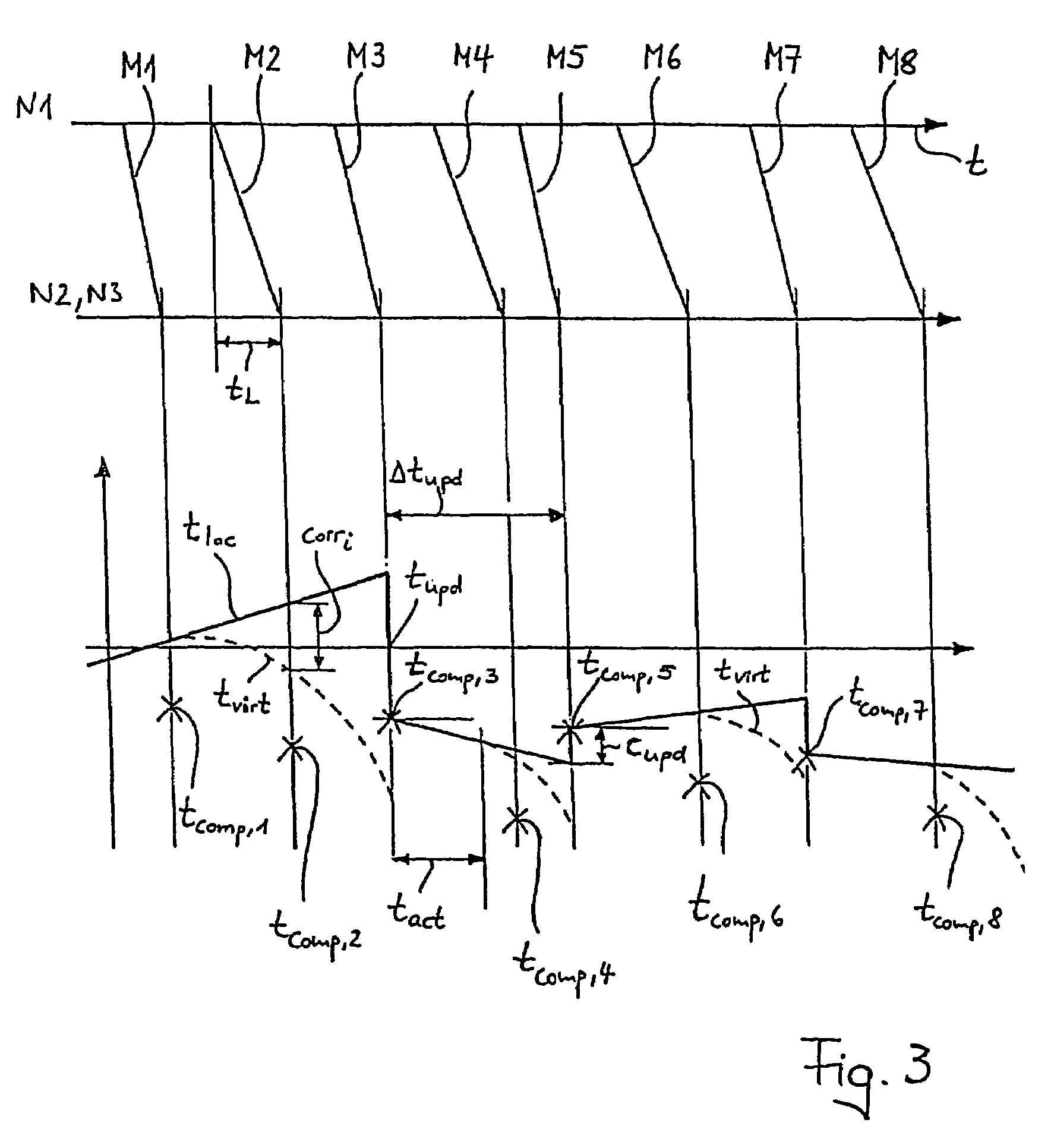
[0031]FIG. 1 shows a number of nodes N1, N2, N3, N4, N5, N6, N7, which are connected to one another by intermediate (sub-)networks—in this case the networks NW1, NW2 and NW3. The arrows symbolically represent the direction in which time messages are transported from a node via a network to another node.

[0032]First of all, only the nodes N1-N3 and the (sub-) network NW1 located in between them will be considered, in a first section. The node N1 in this section under consideration is a higher-level node (“master”), which sends time messages via the network NW1 to the lower-level nodes N2 and N3 (“slave”).

[0033]These time messages each contain the local time at the higher-level node, at that time at which they are sent, as can be seen in the left-hand third of FIG. 2 (in addition, they may also contain a reference to a global reference time, for example UTC or GMT) . By way of example, the illustration in FIG. 2 shows that a time message M1-M4 is sent via the network NW1 to the lower-l...


PUM


Abstract

The invention relates to a method for synchronization in networks, whereby the local time (tloc) which is valid at the particular node, is updated at different nodes. For that purpose, timing messages are regularly transmitted by a freely selectable superior node (N1; N3; N6) and only by a superior node to an inferior node N2, N3; N4-N6; N7), which receives the timing messages M1-M8) and analyzes said messages for updating the local time (tloc) thereof. A minimum propagation time (dmin) is determined for a timing message (M1-M8) between an inferior node (N1;N3;N6) and a superior node (N2, N3; N4-N6; N7). When the inferior node (N2, N3; N4-N6; N7) receives a timing message (M1-M8), said inferior node extracts the local time of the superior node (N1; N3), which is contained in said timing message (M1-M8) and adds the minimum propagation time (dmin) thereto, in order to generate a reference time (tcomp,1-tcomp,8). Said reference time (tcomp,1-tcomp,8) is then compared with the proper local time (tloc). If the reference time is retarded in relation to the proper local time (tloc), said proper local time (tloc) is not updated. If said reference time is advanced in relation to the proper local time (tloc).

Description

CROSS-REFERENCE TO RELATED APPLICATIONS[0001]The present application claims the benefit of PCT application no. PCT / CH02 / 00580, filed on Oct. 25, 2002 and Swiss patent application no. CH 2188 / 01 filed on Nov. 28, 2001, the entire disclosures of which are incorporated by reference as if set forth in its entirety herein.STATEMENT REGARDING FEDERALLY SPONSORED RESEARCH OR DEVELOPMENT[0002]Not applicableTHE NAMES OF THE PARTIES TO A JOINT RESEARCH AGREEMENT[0003]Not applicableINCORPORATION-BY-REFERENCE OF MATERIAL SUBMITTED ON A COMPACT DISC[0004]Not applicableBACKGROUND OF INVENTION[0005]The invention relates to a method for synchronization in networks, as claimed in the precharacterizing clause of the independent patent claim.[0006]Many applications make use of computer resources (nodes) which are distributed in networks, for example in order to improve the performance and / or the error tolerance. In some of these applications it is necessary to have a common time base for all of the co...

Claims


Application Information

Patent Timeline
IPC IPC(8): G06F15/16G06F15/173H04J3/06
CPCH04J3/0664H04L12/1485H04J3/0673
Inventor BLUM, PHILIPPDICKMANN, GEORG
Owner SMSC HLDG
Why Eureka
Try Eureka