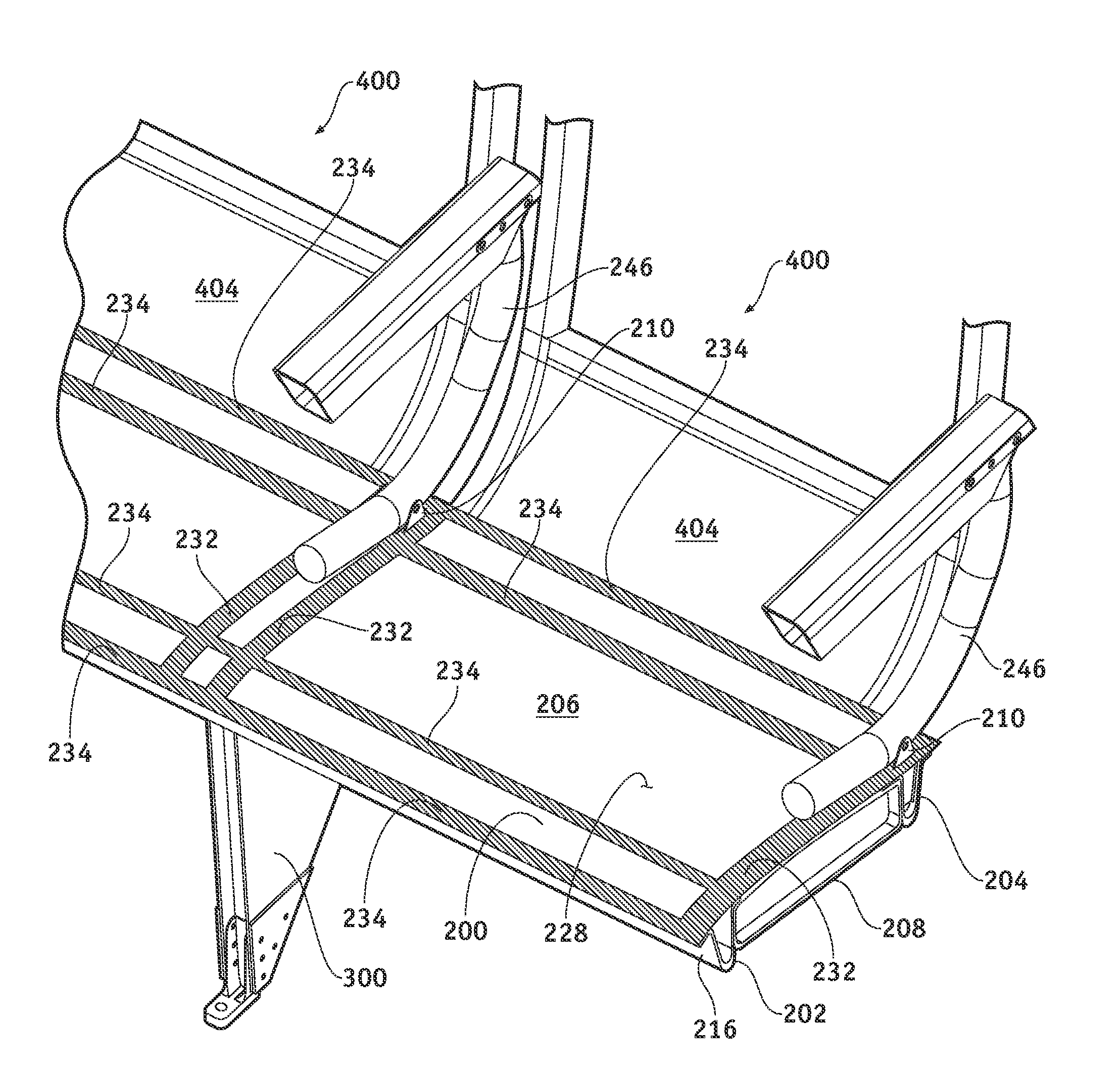
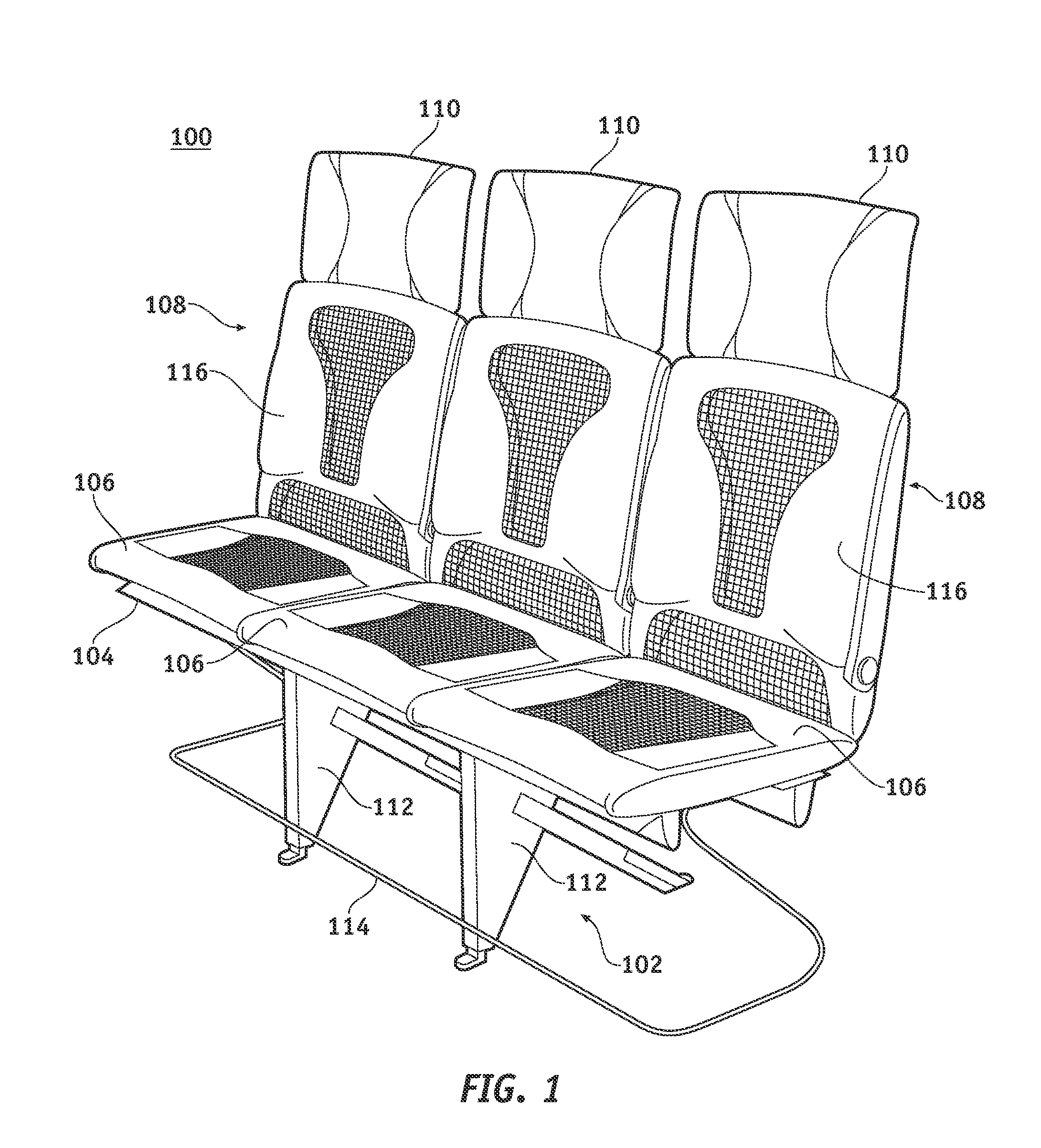
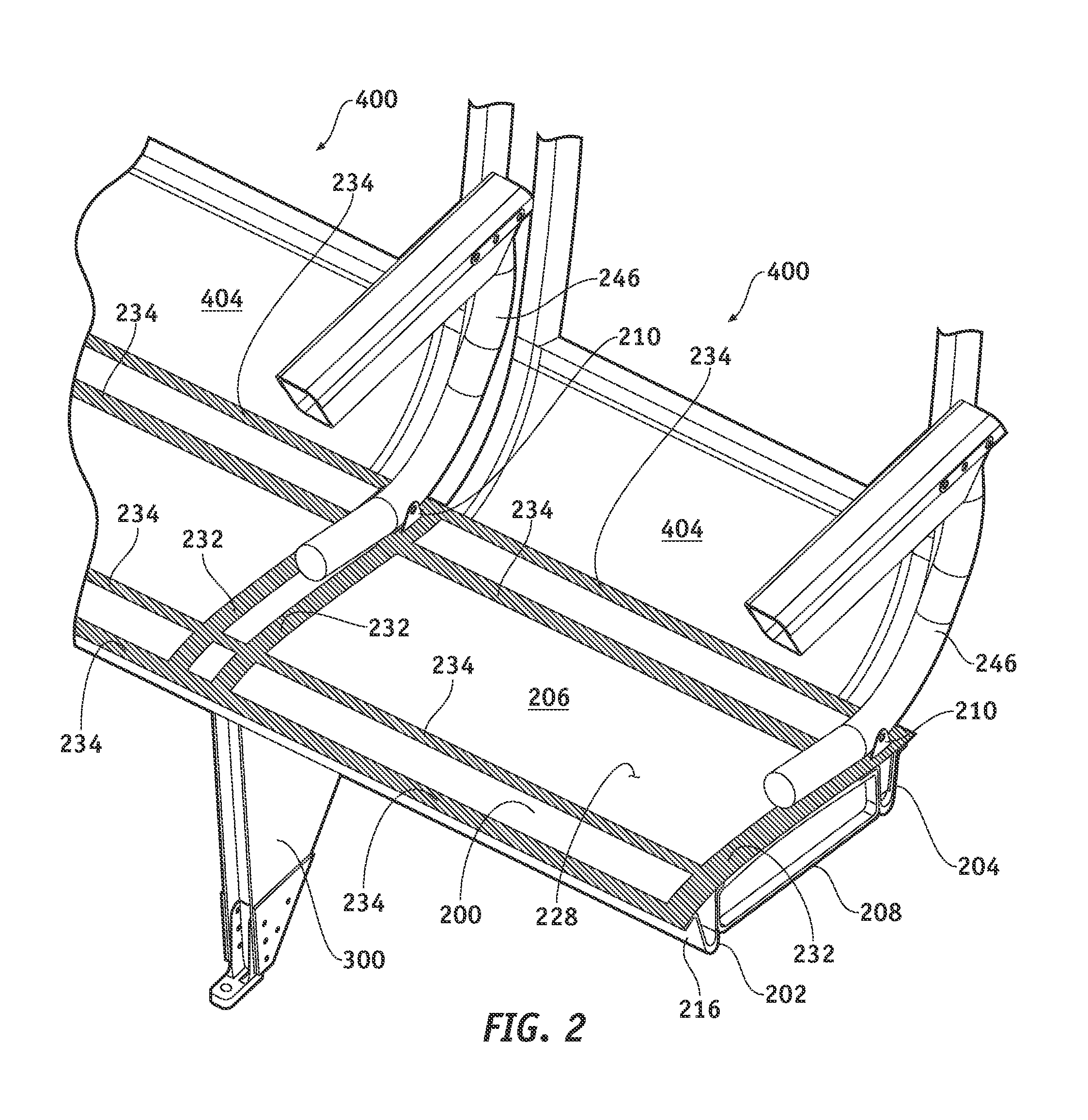
Composite seat pan structure for a lightweight aircraft seat assembly

a lightweight aircraft and passenger seat technology, applied in the field of aircraft components, can solve the problems of consuming precious cabin space, bulky materials and thick padding used in conventional aircraft passenger seats, and reducing the overall weight of the seat, so as to achieve the effect of reducing the size and weigh

Inactive Publication Date: 2010-05-18
THE BOEING CO
View PDF31 Cites 50 Cited by
  • Summary
  • Abstract
  • Description
  • Claims
  • Application Information

AI Technical Summary

Benefits of technology

[0005]An aircraft passenger seat configured in accordance with an example embodiment of the invention includes a lightweight composite construction that provides weight savings and size reduction compared to conventional seats. The composite construction enables the passenger seat to meet required structural specifications in a compact and lightweight configuration. In one embodiment, the lightweight aircraft passenger seat utilizes a composite support leg structure having little or no metal parts. In one embodiment, the lightweight aircraft passenger seat utilizes a composite seat pan assembly having little or no metal parts. In one embodiment, the lightweight aircraft passenger seat utilizes a composite seat back structure. The composite seat pan assembly and the composite seat back structure may be coupled together using a composite flange element that serves as a lightweight hinge element for the seat back structure.

Problems solved by technology

Such components can contribute a significant amount to the overall weight of an aircraft, particularly when the aircraft includes seats for hundreds of passengers.
In practice, the bulky materials and thick padding utilized in conventional aircraft passenger seats consume precious cabin space that could otherwise be used for increased legroom and / or used for additional rows of seats.
Unfortunately, such bulky materials are usually necessary for structural support and thick padding is usually necessary to provide sufficient cushioning for the seated passengers.

Method used


Image

  • Composite seat pan structure for a lightweight aircraft seat assembly
  • Composite seat pan structure for a lightweight aircraft seat assembly
  • Composite seat pan structure for a lightweight aircraft seat assembly

Examples


Embodiment Construction

[0042]The following detailed description is merely illustrative in nature and is not intended to limit the embodiments of the invention or the application and uses of such embodiments. Furthermore, there is no intention to be bound by any expressed or implied theory presented in the preceding technical field, background, brief summary or the following detailed description.

[0043]For the sake of brevity, conventional aspects and techniques related to the manufacture of composite materials (including the handling and processing of particular chemicals, compounds, resins, fibers, and substrates) may not be described in detail herein.

[0044]The following description may refer to elements or nodes or features being “connected” or “coupled” together. As used herein, unless expressly stated otherwise, “connected” means that one element / node / feature is directly joined to (or directly communicates with) another element / node / feature, and not necessarily mechanically. Likewise, unless expressly ...


PUM

PropertyMeasurementUnit
thickaaaaaaaaaa
thickaaaaaaaaaa
thickaaaaaaaaaa

Abstract

An aircraft passenger seat configured in accordance with an embodiment of the invention utilizes composite materials to achieve significant weight savings relative to conventional seat designs. The seat includes one or more lightweight composite support legs, a lightweight composite seat pan, and a lightweight composite seat back structure. The support legs are coupled to the seat pan, which is in turn coupled to the seat back structure. The support legs utilize composite frame elements that are formed as continuous compression molded composite extrusions. The seat pan includes composite fore and aft cross beams that are also formed as continuous compression molded composite extrusions. The aft cross beam includes a rear flange that serves as a flexible “hinge” for the seat back structure. The seat can leverage producible and relatively inexpensive composite manufacturing techniques such that the seat can be economically produced for use as an economy class seat.

Description

TECHNICAL FIELD[0001]Embodiments of the present invention relate generally to aircraft components. More particularly, embodiments of the present invention relate to composite structures, components, and assemblies for a lightweight aircraft passenger seat.BACKGROUND[0002]Commercial aircraft utilize different passenger seating configurations and designs. Historically, aircraft passenger seats have been manufactured using heavy and bulky materials that satisfy certain structural design requirements and passenger comfort requirements. In this regard, conventional aircraft passenger seats include a number of relatively heavy metal components. Such components can contribute a significant amount to the overall weight of an aircraft, particularly when the aircraft includes seats for hundreds of passengers. Weight reduction is becoming increasingly important in modern aircraft design. A reduction in the weight of the aircraft structure may allow the aircraft to carry more fuel, thus extendi...

Claims


Application Information

Patent Timeline
Patent Type & Authority Patents(United States)
IPC IPC(8): B68G7/00B64D11/06
CPCB64D11/06B64D11/0649Y02T50/46Y10T29/481Y10T29/49622Y02T50/40
Inventor KISMARTON, MAX U.FULLERTON, JAMES A.
Owner THE BOEING CO
Why Eureka
Try Eureka