Nozzle for use with thermal spray apparatus

a technology of thermal spray apparatus and nozzle, which is applied in the direction of spray nozzle, coating, plasma technique, etc., can solve the problems of reducing the hardness of the nozzle, and affecting the consistency and quality of the coating materials. , to achieve the effect of improving the consistency and quality of the coating materials, preventing dust and other contaminates, and increasing hardness

Active Publication Date: 2010-05-18
TECHN ENG
View PDF9 Cites 1 Cited by
  • Summary
  • Abstract
  • Description
  • Claims
  • Application Information

AI Technical Summary

Benefits of technology

[0012]A primary object of the present invention is to provide an improved nozzle assembly for use with a thermal spray apparatus for improving the consistency and quality of the coating materials applied therewith.
[0013]Another object of the present invention is to provide a nozzle assembly for use with a thermal spray apparatus including a housing having a tapered portion at an outlet end of the housing that converges towards the outlet of the nozzle for facilitating use of the nozzle assembly in close proximity to a workpiece and angularly disposed with respect thereto.
[0014]It is also an object of the present invention to provide a nozzle assembly including means for conveying pressurized air towards a workpiece adjacent a carrier medium and coating material flowing out of the nozzle. The pressurized air for preventing dust and other contaminates from infiltrating the plasma stream and coating material discharged from the nozzle prior to contacting the workpiece. The pressurized air can be used for cooling the workpiece prior to and after applying the coating material.
[0015]It is also an object of the present invention to provide a nozzle assembly including an improved tip portion of increased hardness for reducing the wear and erosion of the tip portion due to the coating materials and plasma stream passing therethrough.
[0016]A further object of the present invention includes a method for thermal spray application of a coating material to a workpiece including providing a nozzle assembly for spraying a plasma stream carrying heat-softened particles of a coating material towards a workpiece, as well as a jet of pressurized air adjacent to the plasma stream on at least two opposing sides thereof. The jets of pressurized air being directed substantially parallel to the plasma stream for preventing dust and other contaminants from infiltrating the plasma stream containing the coating material prior to contacting the workpiece.

Problems solved by technology

One known problem associated with the plasma / particle confinement zones present in the nozzles of both of the Sokol and Sahoo apparatuses is that the particles of coating materials passing through these confinement zones can become cooled too much prior to exiting the nozzle.
This can cause the particles of coating material to become clumped together resulting in imperfections in the applied coatings.
Another disadvantage of the above-identified prior art nozzle assemblies is that the nozzle assemblies do not include means for cooling the workpiece prior to applying a coating material.
Further, the above-identified prior art nozzles do not include means for enveloping the plasma stream exiting the nozzle with pressurized air for reducing contamination of the plasma stream discharged from the nozzle.

Method used


Image

  • Nozzle for use with thermal spray apparatus
  • Nozzle for use with thermal spray apparatus
  • Nozzle for use with thermal spray apparatus

Examples


Embodiment Construction

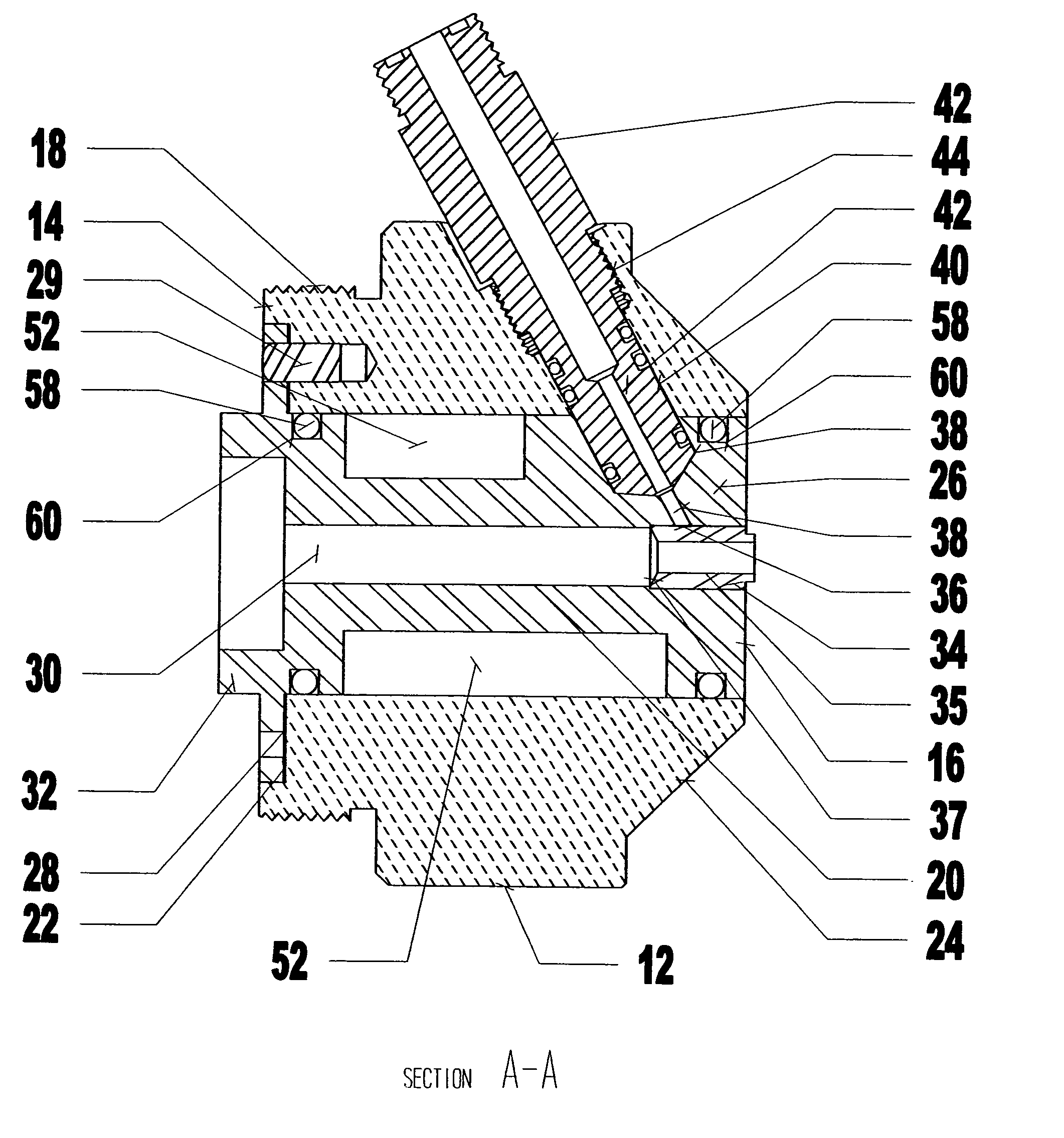
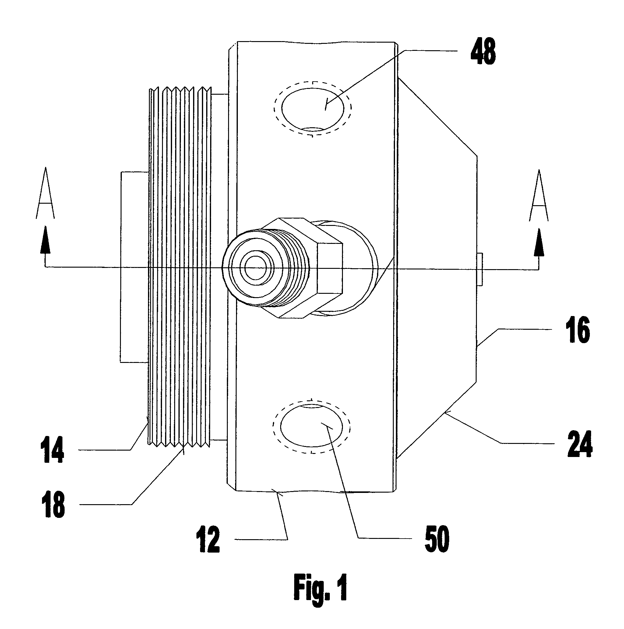
[0024]Referring to the Figures, the present invention nozzle assembly for use with a thermal spray apparatus is generally referred to with the reference numeral 10. The nozzle assembly 10 is attachable to known thermal spray apparatus such as a plasma generator (not shown) and used in conjunction therewith for applying a heat-fusible coating material to a workpiece. The nozzle assembly 10 includes a housing 12 having an inlet end 14 and outlet end 16. The housing 12 is generally cylindrically shaped and includes a threaded portion 18 at the inlet end 14 for coupling the housing and nozzle assembly 10 to a plasma generator.

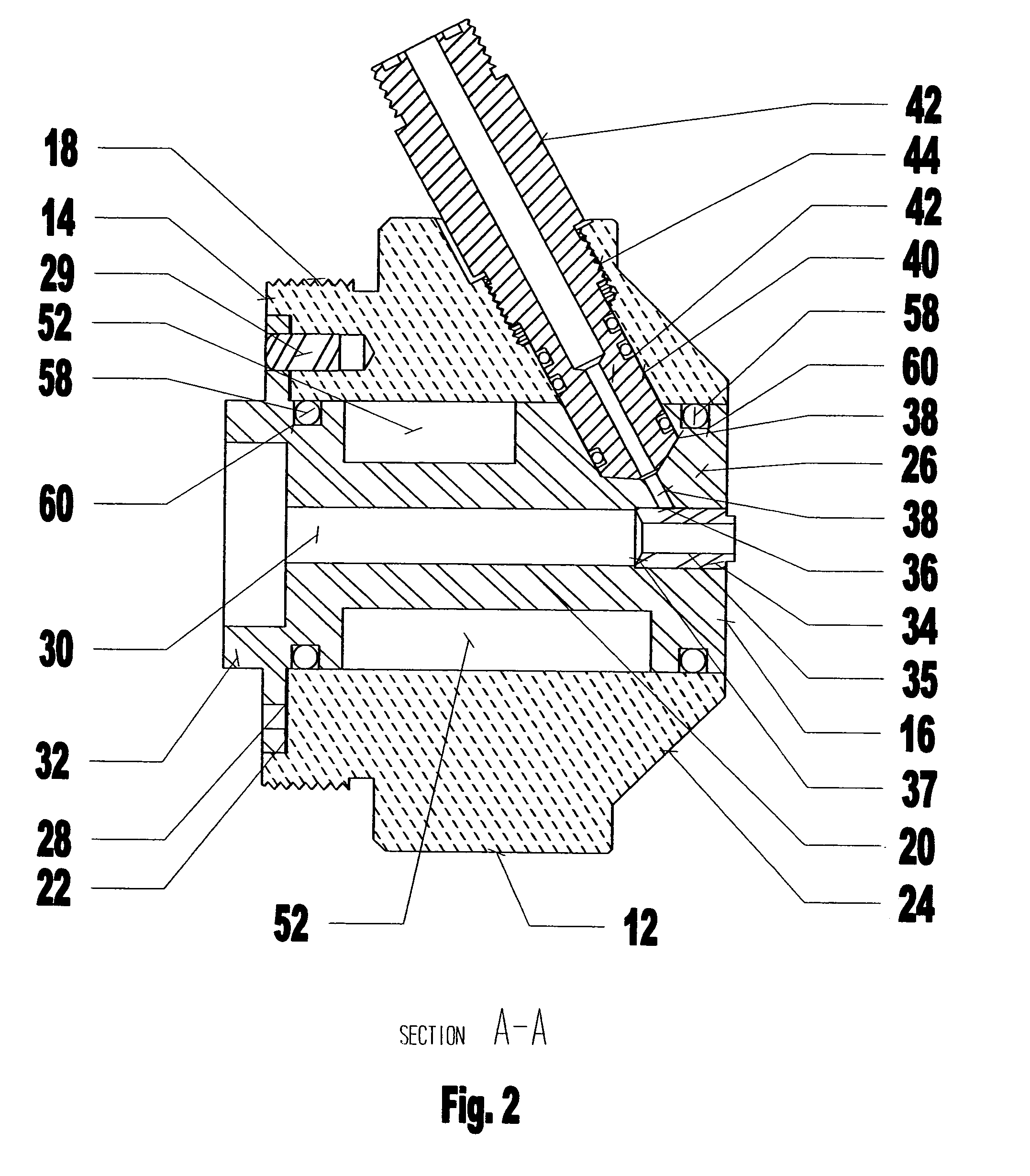
[0025]Referring to FIG. 2, the housing 12 defines a generally cylindrical nozzle opening 20 extending throughout a length of the housing and centered about a central axis X-X defined by the housing. An annular recess 22 is defined by the housing 12 surrounding an inlet end of the nozzle opening 20. The housing 12 further defines a tapered end portion 24 that conver...


PUM

PropertyMeasurementUnit
lengthaaaaaaaaaa
hardnessaaaaaaaaaa
velocitiesaaaaaaaaaa

Abstract

The present invention provides an improved nozzle assembly for use with a thermal spray apparatus for applying a coating to a workpiece. The nozzle assembly including a housing supporting a nozzle defining a gas conduit having an inlet and an outlet at opposing ends of the housing. The inlet for receiving a carrier medium from a thermal spray apparatus. The housing and the nozzle cooperating to define a material feed opening such that the material feed opening intersects the gas conduit proximate the outlet end of the nozzle. The material feed opening being angularly disposed relative to the gas conduit and intersecting the gas conduit proximate the outlet end of the nozzle such that coating material injected into the gas conduit through the material feed opening is heat-softened and propelled towards a workpiece to be coated by the carrier medium flowing outwardly from the nozzle.

Description

FIELD OF THE INVENTION[0001]The present invention generally relates to thermal spray apparatus for spraying molten or heat softened material onto a workpiece at high velocities by means of high temperature carrier mediums. In particular, the present invention is directed to an improved nozzle assembly for use with a plasma generator for directing heated coating materials at high velocity against a workpiece.BACKGROUND OF THE INVENTION[0002]In general, thermal spraying techniques and apparatus for coating metallic substrates are well known in the art. Thermal spray processes normally include the generation of a jet of high temperature carrier medium and the injection of a coating material into the carrier medium. The coating materials are usually powders which become heat-softened or melted by the carrier medium and propelled thereby at high velocities against the surface of a substrate to be coated.[0003]Plasma flame spray apparatus typically include a plasma generator coupled to a ...

Claims


Application Information

Patent Timeline
Patent Type & Authority Patents(United States)
IPC IPC(8): B05B1/24
CPCB05B7/205C23C4/127C23C4/124C23C4/129C23C4/134
Inventor NOUJAIM, MAJED
Owner TECHN ENG
Why Eureka
Try Eureka